

8 Solar Thermal-Powered Adsorption Chiller
119
In this book chapter model equations of a solar thermal powered adsorption chiller
are presented. First, the system is briefly explained in Sect. 8.2. In the next section, the
construction of a flat plate collector is described, which is followed by the derivation
of different heat transfer components to calculate its efficiency. Section 8.4 models an
evacuated tube collector to estimate its dynamic performance. Next model equations
of a typical commercial adsorption chiller are explained, and simulation results of a
10-RTon chiller are presented under specific operating conditions. Finally, the chapter
ends with a conclusion.
8.2 System Description
An adsorption chiller requires low grade heat for its operation. Hence the heat from
flat plate collectors or evacuated tube collectors can drive the system. The main
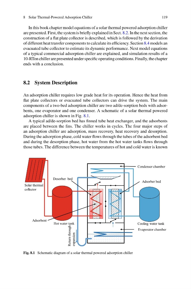
components of a two-bed adsorption chiller are two ad/de-sorption beds with adsorbents, one evaporator and one condenser. A schematic of a solar thermal powered
adsorption chiller is shown in Fig. 8.1.
A typical ad/de-sorption bed has finned tube heat exchanger, and the adsorbents
are placed between the fins. The chiller works in cycles. The four major steps of
an adsorption chiller are adsorption, mass recovery, heat recovery and desorption.
During the adsorption phase, cold water flows through the tubes of the adsorbent bed
and during the desorption phase, hot water from the hot water tanks flows through
those tubes. The difference between the temperatures of hot and cold water is known
Evaporator chamber
Adsorber bed
Desorber bed
Condenser chamber
Adsorbent
Cooling water tank
Hot water tank
Solar thermal
collector
Return through
expansion
Fig. 8.1 Schematic diagram of a solar thermal powered adsorption chiller
119
In this book chapter model equations of a solar thermal powered adsorption chiller
are presented. First, the system is briefly explained in Sect. 8.2. In the next section, the
construction of a flat plate collector is described, which is followed by the derivation
of different heat transfer components to calculate its efficiency. Section 8.4 models an
evacuated tube collector to estimate its dynamic performance. Next model equations
of a typical commercial adsorption chiller are explained, and simulation results of a
10-RTon chiller are presented under specific operating conditions. Finally, the chapter
ends with a conclusion.
8.2 System Description
An adsorption chiller requires low grade heat for its operation. Hence the heat from
flat plate collectors or evacuated tube collectors can drive the system. The main
components of a two-bed adsorption chiller are two ad/de-sorption beds with adsorbents, one evaporator and one condenser. A schematic of a solar thermal powered
adsorption chiller is shown in Fig. 8.1.
A typical ad/de-sorption bed has finned tube heat exchanger, and the adsorbents
are placed between the fins. The chiller works in cycles. The four major steps of
an adsorption chiller are adsorption, mass recovery, heat recovery and desorption.
During the adsorption phase, cold water flows through the tubes of the adsorbent bed
and during the desorption phase, hot water from the hot water tanks flows through
those tubes. The difference between the temperatures of hot and cold water is known
Evaporator chamber
Adsorber bed
Desorber bed
Condenser chamber
Adsorbent
Cooling water tank
Hot water tank
Solar thermal
collector
Return through
expansion
Fig. 8.1 Schematic diagram of a solar thermal powered adsorption chiller