

158
A. Shah
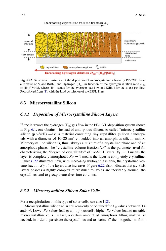
Fig. 6.22 Schematic illustration of the deposition of microcrystalline silicon by PE-CVD, from
a mixture of Silane (SiH 4 ) and Hydrogen (H 2 ), in function of the hydrogen dilution ratio H dil
= [H 2 ]/[SiH 4 ], where [H 2 ] stands for the hydrogen gas flow and [SiH 4 ] for the silane gas flow.
Reproduced from [1], with the kind permission of the EPFL Press
6.3 Microcrystalline Silicon
6.3.1 Deposition of Microcrystalline Silicon Layers
If one increases the hydrogen (H 2 ) gas flow in the PE-CVD deposition system shown
in Fig. 6.1, one obtains—instead of amorphous silicon, so-called “microcrystalline
silicon (µc-Si:H)”—i.e. a material containing tiny crystallites (silicon nanocrystals with a diameter of 10–20 nm) embedded into an amorphous silicon matrix.
Microcrystalline silicon is, thus, always a mixture of a crystalline phase and of an
amorphous phase. The “crystalline volume fraction X C ” is the parameter used for
characterizing the “degree of crystallinity” of µc-Si:H layers: X C = 0 means the
layer is completely amorphous; X C = 1 means the layer is completely crystalline.
Figure 6.22 illustrates how, with increasing hydrogen gas flow, the crystalline volume fraction X C of the layers also increases. Figure 6.22 also indicates that µc-Si:H
layers possess a highly complex microstructure: voids are inevitably formed; the
crystallites tend to group themselves into columns.
6.3.2 Microcrystalline Silicon Solar Cells
For a recapitulation on this type of solar cells, see also [12].
Microcrystalline silicon solar cells can only be obtained for X C values between 0.4
and 0.6. Lower X C values lead to amorphous cells; higher X C values lead to unstable
microcrystalline cells. In fact, a certain amount of amorphous filling material is
needed, in order to passivate the crystallites and to “cement” them together, to form
A. Shah
Fig. 6.22 Schematic illustration of the deposition of microcrystalline silicon by PE-CVD, from
a mixture of Silane (SiH 4 ) and Hydrogen (H 2 ), in function of the hydrogen dilution ratio H dil
= [H 2 ]/[SiH 4 ], where [H 2 ] stands for the hydrogen gas flow and [SiH 4 ] for the silane gas flow.
Reproduced from [1], with the kind permission of the EPFL Press
6.3 Microcrystalline Silicon
6.3.1 Deposition of Microcrystalline Silicon Layers
If one increases the hydrogen (H 2 ) gas flow in the PE-CVD deposition system shown
in Fig. 6.1, one obtains—instead of amorphous silicon, so-called “microcrystalline
silicon (µc-Si:H)”—i.e. a material containing tiny crystallites (silicon nanocrystals with a diameter of 10–20 nm) embedded into an amorphous silicon matrix.
Microcrystalline silicon is, thus, always a mixture of a crystalline phase and of an
amorphous phase. The “crystalline volume fraction X C ” is the parameter used for
characterizing the “degree of crystallinity” of µc-Si:H layers: X C = 0 means the
layer is completely amorphous; X C = 1 means the layer is completely crystalline.
Figure 6.22 illustrates how, with increasing hydrogen gas flow, the crystalline volume fraction X C of the layers also increases. Figure 6.22 also indicates that µc-Si:H
layers possess a highly complex microstructure: voids are inevitably formed; the
crystallites tend to group themselves into columns.
6.3.2 Microcrystalline Silicon Solar Cells
For a recapitulation on this type of solar cells, see also [12].
Microcrystalline silicon solar cells can only be obtained for X C values between 0.4
and 0.6. Lower X C values lead to amorphous cells; higher X C values lead to unstable
microcrystalline cells. In fact, a certain amount of amorphous filling material is
needed, in order to passivate the crystallites and to “cement” them together, to form