

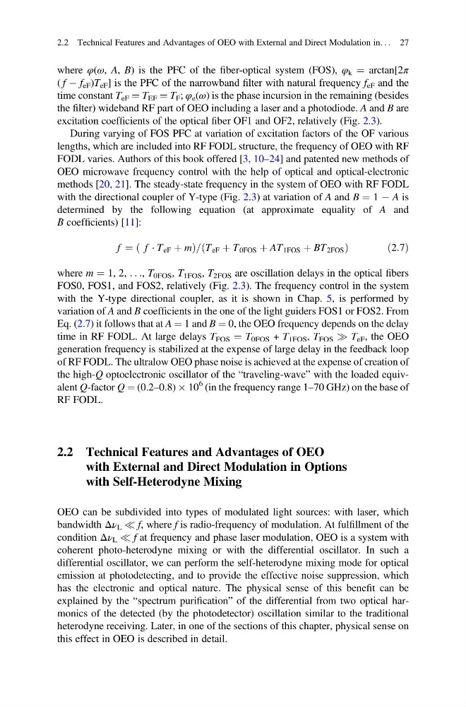
where φ(ω, A, B) is the PFC of the fiber-optical system (FOS), φ k ¼ arctan[2π
( f À f eF )T eF ] is the PFC of the narrowband filter with natural frequency f eF and the
time constant T eF ¼ T EF ¼ T F ; φ e (ω) is the phase incursion in the remaining (besides
the filter) wideband RF part of OEO including a laser and a photodiode. A and B are
excitation coefficients of the optical fiber OF1 and OF2, relatively (Fig. 2.3).
During varying of FOS PFC at variation of excitation factors of the OF various
lengths, which are included into RF FODL structure, the frequency of OEO with RF
FODL varies. Authors of this book offered [3, 10–24] and patented new methods of
OEO microwave frequency control with the help of optical and optical-electronic
methods [20, 21]. The steady-state frequency in the system of OEO with RF FODL
with the directional coupler of Y-type (Fig. 2.3) at variation of A and B ¼ 1 À A is
determined by the following equation (at approximate equality of A and
B coefficients) [11]:
f ¼ f Á T eF þ m
ð
Þ = T eF þ T 0FOS þ AT 1FOS þ BT 2FOS
ð
Þ
ð 2:7Þ
where m ¼ 1, 2, . . ., T 0FOS , T 1FOS , T 2FOS are oscillation delays in the optical fibers
FOS0, FOS1, and FOS2, relatively (Fig. 2.3). The frequency control in the system
with the Y-type directional coupler, as it is shown in Chap. 5, is performed by
variation of A and B coefficients in the one of the light guiders FOS1 or FOS2. From
Eq. (2.7) it follows that at A ¼ 1 and B ¼ 0, the OEO frequency depends on the delay
time in RF FODL. At large delays T FOS ¼ T 0FOS + T 1FOS , T FOS ) T eF , the OEO
generation frequency is stabilized at the expense of large delay in the feedback loop
of RF FODL. The ultralow OEO phase noise is achieved at the expense of creation of
the high-Q optoelectronic oscillator of the “traveling-wave” with the loaded equivalent Q-factor Q ¼ (0.2–0.8) Â 10
6 (in the frequency range 1–70 GHz) on the base of
RF FODL.
2.2 Technical Features and Advantages of OEO
with External and Direct Modulation in Options
with Self-Heterodyne Mixing
OEO can be subdivided into types of modulated light sources: with laser, which
bandwidth Δν L ( f, where f is radio-frequency of modulation. At fulfillment of the
condition Δν L ( f at frequency and phase laser modulation, OEO is a system with
coherent photo-heterodyne mixing or with the differential oscillator. In such a
differential oscillator, we can perform the self-heterodyne mixing mode for optical
emission at photodetecting, and to provide the effective noise suppression, which
has the electronic and optical nature. The physical sense of this benefit can be
explained by the “spectrum purification” of the differential from two optical harmonics of the detected (by the photodetector) oscillation similar to the traditional
heterodyne receiving. Later, in one of the sections of this chapter, physical sense on
this effect in OEO is described in detail.
2.2 Technical Features and Advantages of OEO with External and Direct Modulation in. . . 27
( f À f eF )T eF ] is the PFC of the narrowband filter with natural frequency f eF and the
time constant T eF ¼ T EF ¼ T F ; φ e (ω) is the phase incursion in the remaining (besides
the filter) wideband RF part of OEO including a laser and a photodiode. A and B are
excitation coefficients of the optical fiber OF1 and OF2, relatively (Fig. 2.3).
During varying of FOS PFC at variation of excitation factors of the OF various
lengths, which are included into RF FODL structure, the frequency of OEO with RF
FODL varies. Authors of this book offered [3, 10–24] and patented new methods of
OEO microwave frequency control with the help of optical and optical-electronic
methods [20, 21]. The steady-state frequency in the system of OEO with RF FODL
with the directional coupler of Y-type (Fig. 2.3) at variation of A and B ¼ 1 À A is
determined by the following equation (at approximate equality of A and
B coefficients) [11]:
f ¼ f Á T eF þ m
ð
Þ = T eF þ T 0FOS þ AT 1FOS þ BT 2FOS
ð
Þ
ð 2:7Þ
where m ¼ 1, 2, . . ., T 0FOS , T 1FOS , T 2FOS are oscillation delays in the optical fibers
FOS0, FOS1, and FOS2, relatively (Fig. 2.3). The frequency control in the system
with the Y-type directional coupler, as it is shown in Chap. 5, is performed by
variation of A and B coefficients in the one of the light guiders FOS1 or FOS2. From
Eq. (2.7) it follows that at A ¼ 1 and B ¼ 0, the OEO frequency depends on the delay
time in RF FODL. At large delays T FOS ¼ T 0FOS + T 1FOS , T FOS ) T eF , the OEO
generation frequency is stabilized at the expense of large delay in the feedback loop
of RF FODL. The ultralow OEO phase noise is achieved at the expense of creation of
the high-Q optoelectronic oscillator of the “traveling-wave” with the loaded equivalent Q-factor Q ¼ (0.2–0.8) Â 10
6 (in the frequency range 1–70 GHz) on the base of
RF FODL.
2.2 Technical Features and Advantages of OEO
with External and Direct Modulation in Options
with Self-Heterodyne Mixing
OEO can be subdivided into types of modulated light sources: with laser, which
bandwidth Δν L ( f, where f is radio-frequency of modulation. At fulfillment of the
condition Δν L ( f at frequency and phase laser modulation, OEO is a system with
coherent photo-heterodyne mixing or with the differential oscillator. In such a
differential oscillator, we can perform the self-heterodyne mixing mode for optical
emission at photodetecting, and to provide the effective noise suppression, which
has the electronic and optical nature. The physical sense of this benefit can be
explained by the “spectrum purification” of the differential from two optical harmonics of the detected (by the photodetector) oscillation similar to the traditional
heterodyne receiving. Later, in one of the sections of this chapter, physical sense on
this effect in OEO is described in detail.
2.2 Technical Features and Advantages of OEO with External and Direct Modulation in. . . 27