

the matching optical device for the fiber optical system and the temperatureregulated unit. Measured in experiments average slopes S f of the function f(I bias )
(at equal offsets |I bias À I thr | from the threshold value I thr ) in areas of current
variations upper and lower of the threshold value, are approximately equal for
OEO with the laser diode and are S f ¼ Δf/ΔI bias ¼ 15 kHz/ma.
The optical coupling arising in the directional coupler of Х-type, as shown in
Chap. 4, makes the frequency response f(r) periodical with significant values of the
conversion “control radial displacement–frequency” slope. Depending on the choice
of the “average operating point,” the conversion “radial displacement–frequency”
slope essentially changes and for maximal values is 0.1 MHz/μm for the experimental sample of OEO with RF FODL.
An influence of optical coupling arising in the directional coupler, as shown in
Chap. 4, makes the function f(r) periodical with significant values of the conversion
“radial displacement–frequency” slope. On the other hand, for tasks of development
of frequency stabilized OEO and the frequency control in its electronic part, it is
necessary to use in OEO of the differential RF FODL for coupling of optical
channels of directional couplers of Y-type, in which the longitudinal optical coupling is absent of less by several orders.
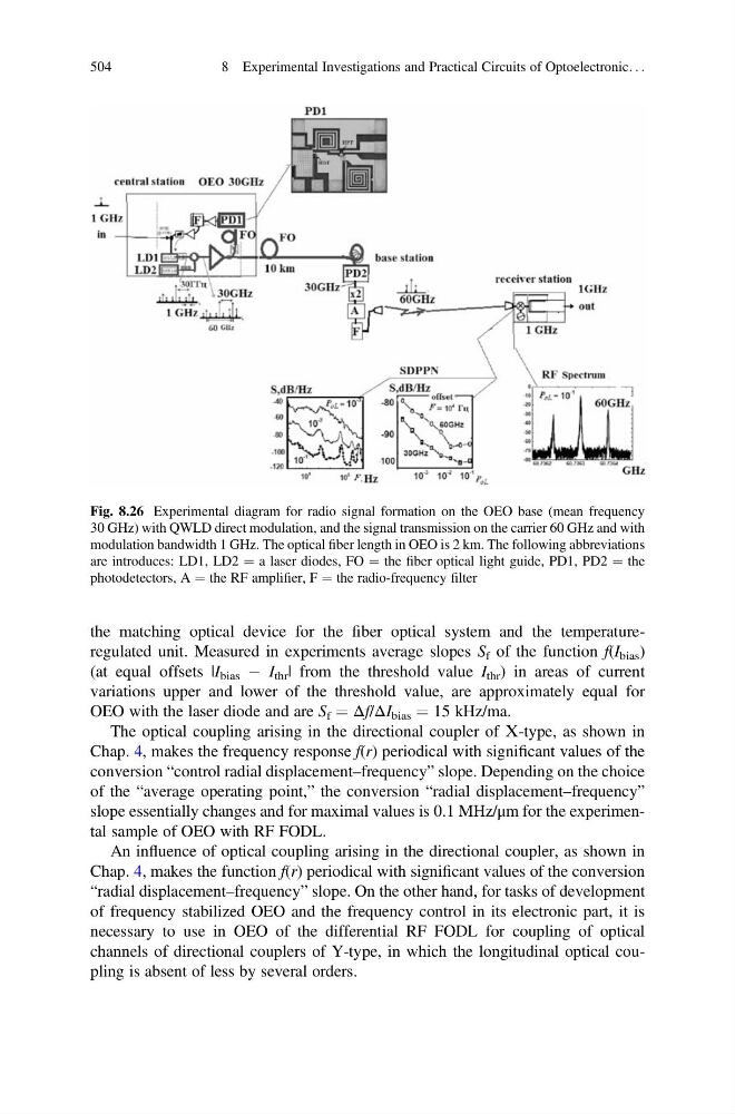
Fig. 8.26 Experimental diagram for radio signal formation on the OEO base (mean frequency
30 GHz) with QWLD direct modulation, and the signal transmission on the carrier 60 GHz and with
modulation bandwidth 1 GHz. The optical fiber length in OEO is 2 km. The following abbreviations
are introduces: LD1, LD2 ¼ a laser diodes, FO ¼ the fiber optical light guide, PD1, PD2 ¼ the
photodetectors, A ¼ the RF amplifier, F ¼ the radio-frequency filter
504
8 Experimental Investigations and Practical Circuits of Optoelectronic. . .
(at equal offsets |I bias À I thr | from the threshold value I thr ) in areas of current
variations upper and lower of the threshold value, are approximately equal for
OEO with the laser diode and are S f ¼ Δf/ΔI bias ¼ 15 kHz/ma.
The optical coupling arising in the directional coupler of Х-type, as shown in
Chap. 4, makes the frequency response f(r) periodical with significant values of the
conversion “control radial displacement–frequency” slope. Depending on the choice
of the “average operating point,” the conversion “radial displacement–frequency”
slope essentially changes and for maximal values is 0.1 MHz/μm for the experimental sample of OEO with RF FODL.
An influence of optical coupling arising in the directional coupler, as shown in
Chap. 4, makes the function f(r) periodical with significant values of the conversion
“radial displacement–frequency” slope. On the other hand, for tasks of development
of frequency stabilized OEO and the frequency control in its electronic part, it is
necessary to use in OEO of the differential RF FODL for coupling of optical
channels of directional couplers of Y-type, in which the longitudinal optical coupling is absent of less by several orders.
Fig. 8.26 Experimental diagram for radio signal formation on the OEO base (mean frequency
30 GHz) with QWLD direct modulation, and the signal transmission on the carrier 60 GHz and with
modulation bandwidth 1 GHz. The optical fiber length in OEO is 2 km. The following abbreviations
are introduces: LD1, LD2 ¼ a laser diodes, FO ¼ the fiber optical light guide, PD1, PD2 ¼ the
photodetectors, A ¼ the RF amplifier, F ¼ the radio-frequency filter
504
8 Experimental Investigations and Practical Circuits of Optoelectronic. . .