

current variation conversion into the indicator frequency is weak at wounding length
of 100 m, while, if the current is more than 1000 A, passes through, we could clearly
register of variations of the OEO indicating frequency.
8.5.7 OEO Application in Lengthy Communication Links
of mm-Wave Range of 60–80 GHz with Large Speed
of the Information Transmission Up to 10 Gbit/s
The important application of OEO is in the lengthy radio communication channels
(including space communications) of mm-wave range (60–80 GHz) with high speed
of information transmission of 10 Gbit/s. Figure 8.25 shows experimental spectra of
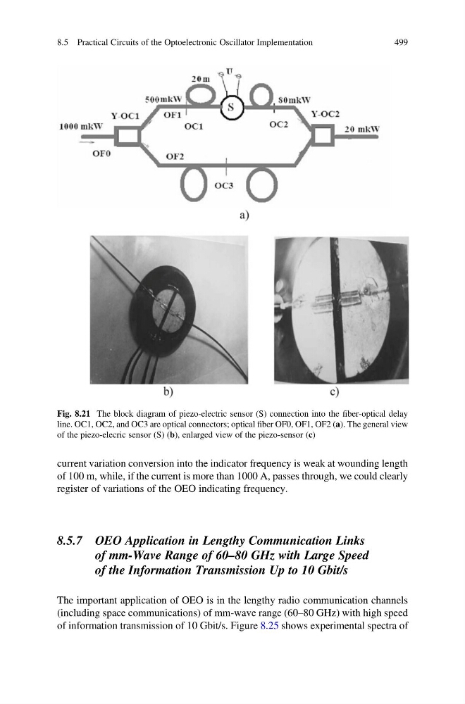
Fig. 8.21 The block diagram of piezo-electric sensor (S) connection into the fiber-optical delay
line. OC1, OC2, and OC3 are optical connectors; optical fiber OF0, OF1, OF2 (a). The general view
of the piezo-elecric sensor (S) (b), enlarged view of the piezo-sensor (c)
8.5 Practical Circuits of the Optoelectronic Oscillator Implementation
499
of 100 m, while, if the current is more than 1000 A, passes through, we could clearly
register of variations of the OEO indicating frequency.
8.5.7 OEO Application in Lengthy Communication Links
of mm-Wave Range of 60–80 GHz with Large Speed
of the Information Transmission Up to 10 Gbit/s
The important application of OEO is in the lengthy radio communication channels
(including space communications) of mm-wave range (60–80 GHz) with high speed
of information transmission of 10 Gbit/s. Figure 8.25 shows experimental spectra of
Fig. 8.21 The block diagram of piezo-electric sensor (S) connection into the fiber-optical delay
line. OC1, OC2, and OC3 are optical connectors; optical fiber OF0, OF1, OF2 (a). The general view
of the piezo-elecric sensor (S) (b), enlarged view of the piezo-sensor (c)
8.5 Practical Circuits of the Optoelectronic Oscillator Implementation
499