

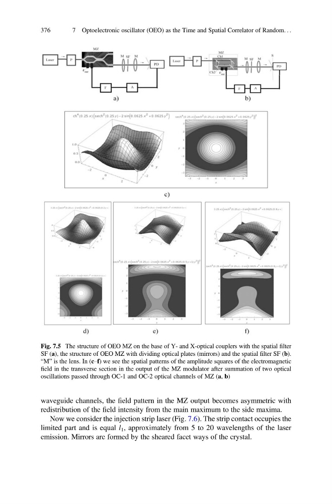
waveguide channels, the field pattern in the MZ output becomes asymmetric with
redistribution of the field intensity from the main maximum to the side maxima.
Now we consider the injection strip laser (Fig. 7.6). The strip contact occupies the
limited part and is equal l 1 , approximately from 5 to 20 wavelengths of the laser
emission. Mirrors are formed by the sheared facet ways of the crystal.
Fig. 7.5 The structure of OEO MZ on the base of Y- and X-optical couplers with the spatial filter
SF (a), the structure of OEO MZ with dividing optical plates (mirrors) and the spatial filter SF (b).
“M” is the lens. In (c–f) we see the spatial patterns of the amplitude squares of the electromagnetic
field in the transverse section in the output of the MZ modulator after summation of two optical
oscillations passed through OC-1 and OC-2 optical channels of MZ (a, b)
376
7 Optoelectronic oscillator (OEO) as the Time and Spatial Correlator of Random. . .
redistribution of the field intensity from the main maximum to the side maxima.
Now we consider the injection strip laser (Fig. 7.6). The strip contact occupies the
limited part and is equal l 1 , approximately from 5 to 20 wavelengths of the laser
emission. Mirrors are formed by the sheared facet ways of the crystal.
Fig. 7.5 The structure of OEO MZ on the base of Y- and X-optical couplers with the spatial filter
SF (a), the structure of OEO MZ with dividing optical plates (mirrors) and the spatial filter SF (b).
“M” is the lens. In (c–f) we see the spatial patterns of the amplitude squares of the electromagnetic
field in the transverse section in the output of the MZ modulator after summation of two optical
oscillations passed through OC-1 and OC-2 optical channels of MZ (a, b)
376
7 Optoelectronic oscillator (OEO) as the Time and Spatial Correlator of Random. . .