

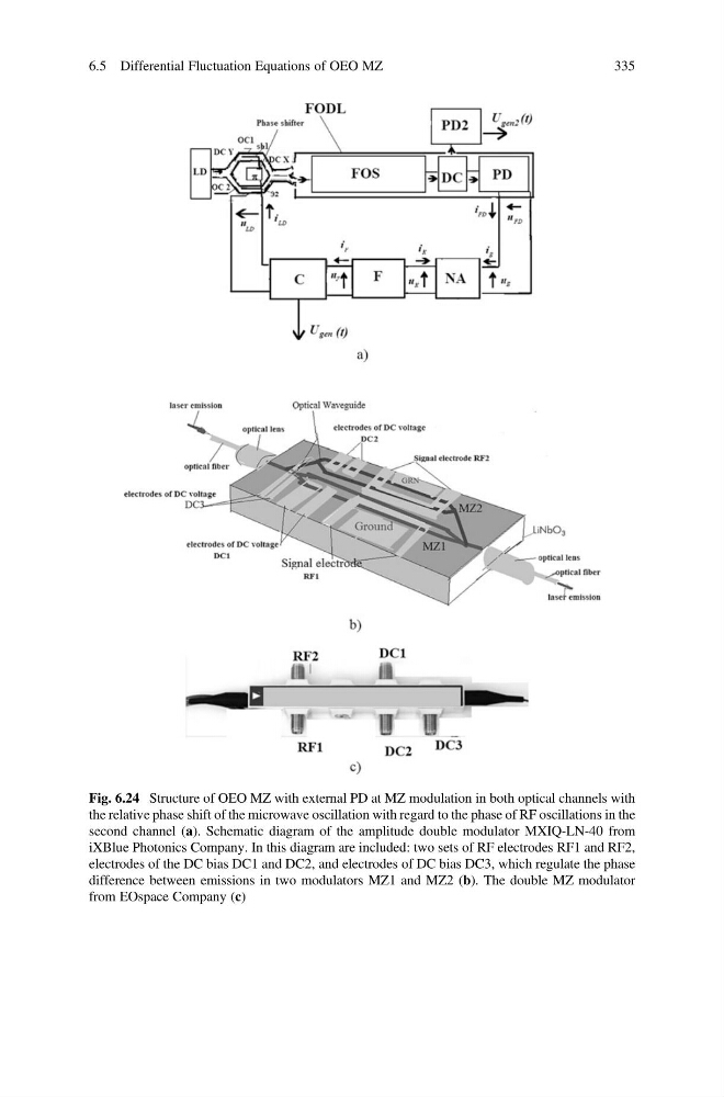
Fig. 6.24 Structure of OEO MZ with external PD at MZ modulation in both optical channels with
the relative phase shift of the microwave oscillation with regard to the phase of RF oscillations in the
second channel (a). Schematic diagram of the amplitude double modulator MXIQ-LN-40 from
iXBlue Photonics Company. In this diagram are included: two sets of RF electrodes RF1 and RF2,
electrodes of the DC bias DC1 and DC2, and electrodes of DC bias DC3, which regulate the phase
difference between emissions in two modulators MZ1 and MZ2 (b). The double MZ modulator
from EOspace Company (c)
6.5 Differential Fluctuation Equations of OEO MZ
335
the relative phase shift of the microwave oscillation with regard to the phase of RF oscillations in the
second channel (a). Schematic diagram of the amplitude double modulator MXIQ-LN-40 from
iXBlue Photonics Company. In this diagram are included: two sets of RF electrodes RF1 and RF2,
electrodes of the DC bias DC1 and DC2, and electrodes of DC bias DC3, which regulate the phase
difference between emissions in two modulators MZ1 and MZ2 (b). The double MZ modulator
from EOspace Company (c)
6.5 Differential Fluctuation Equations of OEO MZ
335