

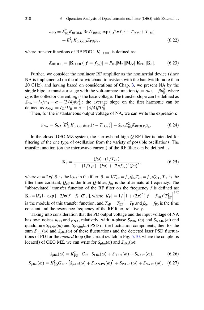
u PD ¼ E
2
0L K 0FOLD Re U 10MZ exp j2π f 0 t þ T FOS þ T 1M
ð
Þ
þ E
2
0L K 0FOLD Z PD μ n ,
ð6:22Þ
where transfer functions of RF FODL K 0FODL is defined as:
K 0FODL ¼ K FODL f ¼ f 0e
ð
Þ
j
j ¼ P 0L M Z
j j M eZ
j
j K PD
j
jK F
j j:
ð6:23Þ
Further, we consider the nonlinear RF amplifier as the noninertial device (since
NA is implemented on the ultra-wideband transistors with the bandwidth more than
20 GHz), and having based on considerations of Chap. 3, we present NA by the
single bipolar transistor stage with the volt-ampere function i C ¼ αu B À βu
3
B , where
i C is the collector current, u B is the base voltage. The transfer slope can be defined as
S NA ¼ i C =u B ¼ α À 3=4
ð Þβu
2
B ; the average slope on the first harmonic can be
defined as S NA1 ¼ I C =U B ¼ α À 3=4
ð
ÞβU
2
B .
Then, for the instantaneous output voltage of NA, we can write the expression:
u NA ¼ S NA E
2
0L K 0FOLD u PD t À T FOS
ð
Þ
Â
à þ S NA E
2
0L K 0FOLD μ n :
ð6:24Þ
In the closed OEO MZ system, the narrowband high-Q RF filter is intended for
filtering of the one type of oscillation from the variety of possible oscillations. The
transfer function (on the microwave current) of the RF filter can be defined as
K F ¼
jω
ð Þ Á 1=T eF
ð
Þ
1 þ 1=T eF
ð
ÞÁ jω
ð Þ þ 2π f 0e
ð
Þ
2 jω
ð Þ
2
,
ð6:25Þ
where ω ¼ 2πf, δ e is the loss in the filter: δ e ¼ 1/T eF ¼ f 0e /f 0e T eF ¼ f 0e /Q eF , T eF is the
filter time constant, Q eF is the filter Q-filter, f 0e is the filter natural frequency. The
“abbreviated” transfer function of the RF filter on the frequency f is defined as:
K F ¼ |K F | Á exp [À2jπ( f À f F0 )T EF ], where K F
j j ¼ 1= 1 þ 2π
ð Þ
2 f À f F0
ð
Þ
2 T
2
EF
h
i 1=2
is the module of this transfer function, and T eF ¼ T EF ¼ T F and f 0e ¼ f F0 is the time
constant and the resonance frequency of the RF filter, relatively.
Taking into consideration that the PD output voltage and the input voltage of NA
has own noises μ PD and μ NA , relatively, with in-phase S PDRe (ω) and S NARe (ω) and
quadrature S PDIm (ω) and S NAIm (ω) PSD of the fluctuation components, then for the
sum S μIm (ω) and S μRe (ω) of these fluctuations and the detected laser PSD fluctuations of PD for the opened loop (the circuit switch in Fig. 5.10, where the coupler is
located) of OEO MZ, we can write for S μIm (ω) and S μRe (ω):
S μIm ω
ð Þ ¼ K
2
PD Á G 12 Á S LIm ω
ð Þ þ S PDIm ω
ð Þ þ S NAIm ω
ð Þ,
ð6:26Þ
S μ Re ω
ð Þ ¼ K
2
PD G 12 Á S μAN ω
ð Þ þ S μAN‐PN ω
ð Þ
Â
à þ S PD Re ω
ð Þ þ S NA Re ω
ð Þ, ð6:27Þ
310
6 Operation Analysis of Optoelectronic oscillator (OEO) with External. . .
2
0L K 0FOLD Re U 10MZ exp j2π f 0 t þ T FOS þ T 1M
ð
Þ
þ E
2
0L K 0FOLD Z PD μ n ,
ð6:22Þ
where transfer functions of RF FODL K 0FODL is defined as:
K 0FODL ¼ K FODL f ¼ f 0e
ð
Þ
j
j ¼ P 0L M Z
j j M eZ
j
j K PD
j
jK F
j j:
ð6:23Þ
Further, we consider the nonlinear RF amplifier as the noninertial device (since
NA is implemented on the ultra-wideband transistors with the bandwidth more than
20 GHz), and having based on considerations of Chap. 3, we present NA by the
single bipolar transistor stage with the volt-ampere function i C ¼ αu B À βu
3
B , where
i C is the collector current, u B is the base voltage. The transfer slope can be defined as
S NA ¼ i C =u B ¼ α À 3=4
ð Þβu
2
B ; the average slope on the first harmonic can be
defined as S NA1 ¼ I C =U B ¼ α À 3=4
ð
ÞβU
2
B .
Then, for the instantaneous output voltage of NA, we can write the expression:
u NA ¼ S NA E
2
0L K 0FOLD u PD t À T FOS
ð
Þ
Â
à þ S NA E
2
0L K 0FOLD μ n :
ð6:24Þ
In the closed OEO MZ system, the narrowband high-Q RF filter is intended for
filtering of the one type of oscillation from the variety of possible oscillations. The
transfer function (on the microwave current) of the RF filter can be defined as
K F ¼
jω
ð Þ Á 1=T eF
ð
Þ
1 þ 1=T eF
ð
ÞÁ jω
ð Þ þ 2π f 0e
ð
Þ
2 jω
ð Þ
2
,
ð6:25Þ
where ω ¼ 2πf, δ e is the loss in the filter: δ e ¼ 1/T eF ¼ f 0e /f 0e T eF ¼ f 0e /Q eF , T eF is the
filter time constant, Q eF is the filter Q-filter, f 0e is the filter natural frequency. The
“abbreviated” transfer function of the RF filter on the frequency f is defined as:
K F ¼ |K F | Á exp [À2jπ( f À f F0 )T EF ], where K F
j j ¼ 1= 1 þ 2π
ð Þ
2 f À f F0
ð
Þ
2 T
2
EF
h
i 1=2
is the module of this transfer function, and T eF ¼ T EF ¼ T F and f 0e ¼ f F0 is the time
constant and the resonance frequency of the RF filter, relatively.
Taking into consideration that the PD output voltage and the input voltage of NA
has own noises μ PD and μ NA , relatively, with in-phase S PDRe (ω) and S NARe (ω) and
quadrature S PDIm (ω) and S NAIm (ω) PSD of the fluctuation components, then for the
sum S μIm (ω) and S μRe (ω) of these fluctuations and the detected laser PSD fluctuations of PD for the opened loop (the circuit switch in Fig. 5.10, where the coupler is
located) of OEO MZ, we can write for S μIm (ω) and S μRe (ω):
S μIm ω
ð Þ ¼ K
2
PD Á G 12 Á S LIm ω
ð Þ þ S PDIm ω
ð Þ þ S NAIm ω
ð Þ,
ð6:26Þ
S μ Re ω
ð Þ ¼ K
2
PD G 12 Á S μAN ω
ð Þ þ S μAN‐PN ω
ð Þ
Â
à þ S PD Re ω
ð Þ þ S NA Re ω
ð Þ, ð6:27Þ
310
6 Operation Analysis of Optoelectronic oscillator (OEO) with External. . .