

16 Integration of Detectors into a Large Experiment: Examples from ATLAS. . .
743
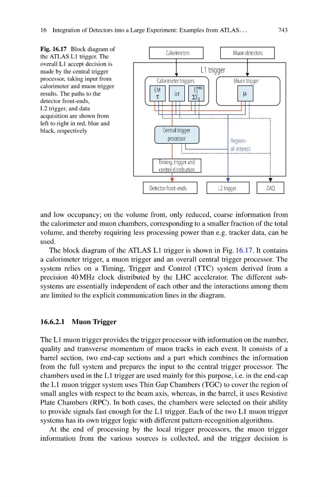
Fig. 16.17 Block diagram of
the ATLAS L1 trigger. The
overall L1 accept decision is
made by the central trigger
processor, taking input from
calorimeter and muon trigger
results. The paths to the
detector front-ends,
L2 trigger, and data
acquisition are shown from
left to right in red, blue and
black, respectively
Regionsof-interest
Calorimeters
Calorimeter triggers
EM
Jet
μ
E T
miss
ΣE T
τ
Muon trigger
Central trigger
processor
Detector front-ends
L2 trigger
DAQ
Timing, trigger and
control distribution
Muon detectors
L1 trigger
and low occupancy; on the volume front, only reduced, coarse information from
the calorimeter and muon chambers, corresponding to a smaller fraction of the total
volume, and thereby requiring less processing power than e.g. tracker data, can be
used.
The block diagram of the ATLAS L1 trigger is shown in Fig. 16.17. It contains
a calorimeter trigger, a muon trigger and an overall central trigger processor. The
system relies on a Timing, Trigger and Control (TTC) system derived from a
precision 40 MHz clock distributed by the LHC accelerator. The different subsystems are essentially independent of each other and the interactions among them
are limited to the explicit communication lines in the diagram.
16.6.2.1 Muon Trigger
The L1 muon trigger provides the trigger processor with information on the number,
quality and transverse momentum of muon tracks in each event. It consists of a
barrel section, two end-cap sections and a part which combines the information
from the full system and prepares the input to the central trigger processor. The
chambers used in the L1 trigger are used mainly for this purpose, i.e. in the end-cap
the L1 muon trigger system uses Thin Gap Chambers (TGC) to cover the region of
small angles with respect to the beam axis, whereas, in the barrel, it uses Resistive
Plate Chambers (RPC). In both cases, the chambers were selected on their ability
to provide signals fast enough for the L1 trigger. Each of the two L1 muon trigger
systems has its own trigger logic with different pattern-recognition algorithms.
At the end of processing by the local trigger processors, the muon trigger
information from the various sources is collected, and the trigger decision is