

734
D. Froidevaux
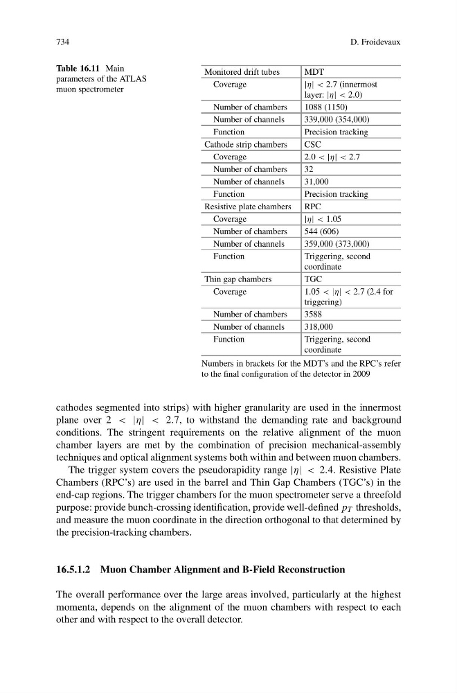
Table 16.11 Main
parameters of the ATLAS
muon spectrometer
Monitored drift tubes
MDT
Coverage
|η| < 2.7 (innermost
layer: |η| < 2.0)
Number of chambers
1088 (1150)
Number of channels
339,000 (354,000)
Function
Precision tracking
Cathode strip chambers
CSC
Coverage
2.0 < |η| < 2.7
Number of chambers
32
Number of channels
31,000
Function
Precision tracking
Resistive plate chambers RPC
Coverage
|η| < 1.05
Number of chambers
544 (606)
Number of channels
359,000 (373,000)
Function
Triggering, second
coordinate
Thin gap chambers
TGC
Coverage
1.05 < |η| < 2.7 (2.4 for
triggering)
Number of chambers
3588
Number of channels
318,000
Function
Triggering, second
coordinate
Numbers in brackets for the MDT’s and the RPC’s refer
to the final configuration of the detector in 2009
cathodes segmented into strips) with higher granularity are used in the innermost
plane over 2 < |η| < 2.7, to withstand the demanding rate and background
conditions. The stringent requirements on the relative alignment of the muon
chamber layers are met by the combination of precision mechanical-assembly
techniques and optical alignment systems both within and between muon chambers.
The trigger system covers the pseudorapidity range |η| < 2.4. Resistive Plate
Chambers (RPC’s) are used in the barrel and Thin Gap Chambers (TGC’s) in the
end-cap regions. The trigger chambers for the muon spectrometer serve a threefold
purpose: provide bunch-crossing identification, provide well-defined p T thresholds,
and measure the muon coordinate in the direction orthogonal to that determined by
the precision-tracking chambers.
16.5.1.2 Muon Chamber Alignment and B-Field Reconstruction
The overall performance over the large areas involved, particularly at the highest
momenta, depends on the alignment of the muon chambers with respect to each
other and with respect to the overall detector.