

16 Integration of Detectors into a Large Experiment: Examples from ATLAS. . .
719
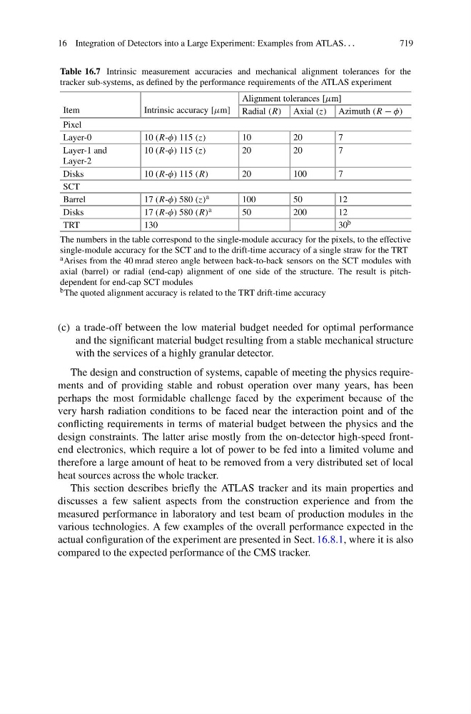
Table 16.7 Intrinsic measurement accuracies and mechanical alignment tolerances for the
tracker sub-systems, as defined by the performance requirements of the ATLAS experiment
Item
Intrinsic accuracy [μm]
Alignment tolerances [μm]
Radial (R) Axial (z) Azimuth (R − φ)
Pixel
Layer-0
10 (R-φ) 115 (z)
10
20
7
Layer-1 and
Layer-2
10 (R-φ) 115 (z)
20
20
7
Disks
10 (R-φ) 115 (R)
20
100
7
SCT
Barrel
17 (R-φ) 580 (z) a
100
50
12
Disks
17 (R-φ) 580 (R) a
50
200
12
TRT
130
30 b
The numbers in the table correspond to the single-module accuracy for the pixels, to the effective
single-module accuracy for the SCT and to the drift-time accuracy of a single straw for the TRT
a Arises from the 40 mrad stereo angle between back-to-back sensors on the SCT modules with
axial (barrel) or radial (end-cap) alignment of one side of the structure. The result is pitchdependent for end-cap SCT modules
b The quoted alignment accuracy is related to the TRT drift-time accuracy
(c) a trade-off between the low material budget needed for optimal performance
and the significant material budget resulting from a stable mechanical structure
with the services of a highly granular detector.
The design and construction of systems, capable of meeting the physics requirements and of providing stable and robust operation over many years, has been
perhaps the most formidable challenge faced by the experiment because of the
very harsh radiation conditions to be faced near the interaction point and of the
conflicting requirements in terms of material budget between the physics and the
design constraints. The latter arise mostly from the on-detector high-speed frontend electronics, which require a lot of power to be fed into a limited volume and
therefore a large amount of heat to be removed from a very distributed set of local
heat sources across the whole tracker.
This section describes briefly the ATLAS tracker and its main properties and
discusses a few salient aspects from the construction experience and from the
measured performance in laboratory and test beam of production modules in the
various technologies. A few examples of the overall performance expected in the
actual configuration of the experiment are presented in Sect. 16.8.1, where it is also
compared to the expected performance of the CMS tracker.