

704
D. Froidevaux
Table 16.3 Main parameters of the CMS and ATLAS magnet systems
Parameter
CMS
ATLAS
solenoid
Solenoid
Barrel toroid
End-cap toroids
Inner diameter
5.9 m
2.4 m
9.4 m
1.7 m
Outer diameter
6.5 m
2.6 m
20.1 m
10.7 m
Axial length
12.9 m
5.3 m
25.3 m
5.0 m
Number of coils
1
1
8
8
Number of turns per coil
2168
1173
120
116
Conductor size [mm 2 ]
64 × 22
30 × 4.25
57 × 12
41 × 12
Bending power
4 T · m
2 T · m
3 T · m
6 T · m
Current
19.5 kA
7.6 kA
20.5 kA
20.0 kA
Stored energy
2700 MJ
38 MJ
1080 MJ
206 MJ
E/M [kJ/kg]
12
10
8
6
4
2
0
10000
1000
100
SDC prototype
Stored energy E [MJ]
10
1
ATLAS solenoid
ALEPH
CDF
ZEUS
TOPAZ
VENUS
H1
CLEO-II
DELPHI
CMS solenoid
ATLAS barrel toroid
ATLAS end-cap toroids
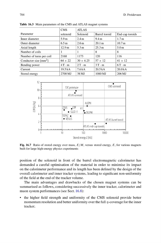
Fig. 16.7 Ratio of stored energy over mass, E/M, versus stored energy, E, for various magnets
built for large high-energy physics experiments
position of the solenoid in front of the barrel electromagnetic calorimeter has
demanded a careful optimisation of the material in order to minimise its impact
on the calorimeter performance and its length has been defined by the design of the
overall calorimeter and inner tracker systems, leading to significant non-uniformity
of the field at the end of the tracker volume.
The main advantages and drawbacks of the chosen magnet systems can be
summarised as follows, considering successively the inner tracker, calorimeter and
muon system performances (see Sect. 16.8):
• the higher field strength and uniformity of the CMS solenoid provide better
momentum resolution and better uniformity over the full η-coverage for the inner
tracker;