

6 Calorimetry
273
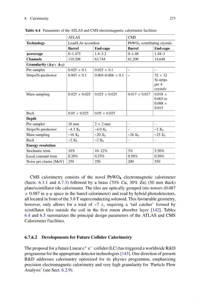
Table 6.4 Parameters of the ATLAS and CMS electromagnetic calorimeter facilities
ATLAS
CMS
Technology
Lead/LAr accordion
PbWO 4 scintillating crystals
Barrel
End-caps
Barrel
End-caps
ηcoverage
0–1.475
1.4–3.2
0–1.48
1.48–3
Channels
110,208
63,744
61,200
14,648
Granularity (
Pre-sampler
0.025 × 0.1
0.025 × 0.1
–
–
Strips/Si-preshower
0.003 × 0.1
0.003–0.006 × 0.1 –
32 × 32
Si-strips
per 4
crystals
Main sampling
0.025 × 0.025 0.025 × 0.025
0.017 × 0.017 0.018 ×
0.003 to
0.088 ×
0.015
Back
0.05 × 0.025
0.05 × 0.025
Depth
Pre-sampler
10 mm
2 × 2 mm
–
–
Strips/Si-preshower
~4.3 X 0
~4.0 X 0
–
~3 X 0
Main sampling
~16 X 0
~20 X 0
~26 X 0
~25 X 0
Back
~2 X 0
~2 X 0
–
–
Energy resolution
Stochastic term
10%
10–12%
3%
5.50%
Local constant term
0.20%
0.35%
0.50%
0.50%
Noise per cluster [MeV] 250
250
200
550
CMS calorimetry consists of the novel PbWO 4 electromagnetic calorimeter
(Sects. 6.3.1 and 6.7.3) followed by a brass (70% Cu, 30% Zn) (50 mm thick)
plate/scintillator tile calorimeter. The tiles are optically grouped into towers (0.087
× 0.087 in η-ϕ space in the barrel calorimeter) and read by hybrid photodetectors,
all located in front of the 3.8 T superconducting solenoid. This favourable geometry,
however, only allows for a total of ~7 λ, requiring a ‘tail catcher’ formed by
scintillator tiles outside the coil in the first muon absorber layer [142]. Tables
6.4 and 6.5 summarizes the principal design parameters of the ATLAS and CMS
Calorimeter Facilities.
6.7.6.2 Developments for Future Collider Calorimetry
The proposal for a future Linear e + e − collider (LC) has triggered a worldwide R&D
programme for the appropriate detector technologies [143]. One direction of present
R&D addresses calorimetry optimized for its physics programme, emphasizing
precision electromagnetic calorimetry and very high granularity for ‘Particle Flow
Analysis’ (see Sect. 6.2.9).
273
Table 6.4 Parameters of the ATLAS and CMS electromagnetic calorimeter facilities
ATLAS
CMS
Technology
Lead/LAr accordion
PbWO 4 scintillating crystals
Barrel
End-caps
Barrel
End-caps
ηcoverage
0–1.475
1.4–3.2
0–1.48
1.48–3
Channels
110,208
63,744
61,200
14,648
Granularity (
Pre-sampler
0.025 × 0.1
0.025 × 0.1
–
–
Strips/Si-preshower
0.003 × 0.1
0.003–0.006 × 0.1 –
32 × 32
Si-strips
per 4
crystals
Main sampling
0.025 × 0.025 0.025 × 0.025
0.017 × 0.017 0.018 ×
0.003 to
0.088 ×
0.015
Back
0.05 × 0.025
0.05 × 0.025
Depth
Pre-sampler
10 mm
2 × 2 mm
–
–
Strips/Si-preshower
~4.3 X 0
~4.0 X 0
–
~3 X 0
Main sampling
~16 X 0
~20 X 0
~26 X 0
~25 X 0
Back
~2 X 0
~2 X 0
–
–
Energy resolution
Stochastic term
10%
10–12%
3%
5.50%
Local constant term
0.20%
0.35%
0.50%
0.50%
Noise per cluster [MeV] 250
250
200
550
CMS calorimetry consists of the novel PbWO 4 electromagnetic calorimeter
(Sects. 6.3.1 and 6.7.3) followed by a brass (70% Cu, 30% Zn) (50 mm thick)
plate/scintillator tile calorimeter. The tiles are optically grouped into towers (0.087
× 0.087 in η-ϕ space in the barrel calorimeter) and read by hybrid photodetectors,
all located in front of the 3.8 T superconducting solenoid. This favourable geometry,
however, only allows for a total of ~7 λ, requiring a ‘tail catcher’ formed by
scintillator tiles outside the coil in the first muon absorber layer [142]. Tables
6.4 and 6.5 summarizes the principal design parameters of the ATLAS and CMS
Calorimeter Facilities.
6.7.6.2 Developments for Future Collider Calorimetry
The proposal for a future Linear e + e − collider (LC) has triggered a worldwide R&D
programme for the appropriate detector technologies [143]. One direction of present
R&D addresses calorimetry optimized for its physics programme, emphasizing
precision electromagnetic calorimetry and very high granularity for ‘Particle Flow
Analysis’ (see Sect. 6.2.9).