

652
K. Hübner et al.
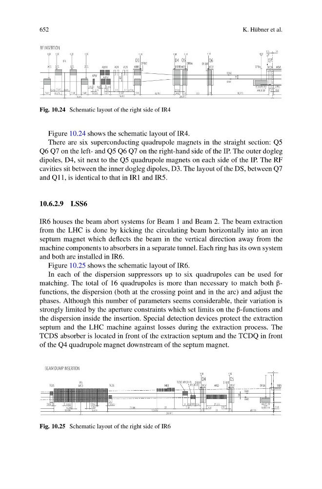
Fig. 10.24 Schematic layout of the right side of IR4
Figure 10.24 shows the schematic layout of IR4.
There are six superconducting quadrupole magnets in the straight section: Q5
Q6 Q7 on the left- and Q5 Q6 Q7 on the right-hand side of the IP. The outer dogleg
dipoles, D4, sit next to the Q5 quadrupole magnets on each side of the IP. The RF
cavities sit between the inner dogleg dipoles, D3. The layout of the DS, between Q7
and Q11, is identical to that in IR1 and IR5.
10.6.2.9 LSS6
IR6 houses the beam abort systems for Beam 1 and Beam 2. The beam extraction
from the LHC is done by kicking the circulating beam horizontally into an iron
septum magnet which deflects the beam in the vertical direction away from the
machine components to absorbers in a separate tunnel. Each ring has its own system
and both are installed in IR6.
Figure 10.25 shows the schematic layout of IR6.
In each of the dispersion suppressors up to six quadrupoles can be used for
matching. The total of 16 quadrupoles is more than necessary to match both βfunctions, the dispersion (both at the crossing point and in the arc) and adjust the
phases. Although this number of parameters seems considerable, their variation is
strongly limited by the aperture constraints which set limits on the β-functions and
the dispersion inside the insertion. Special detection devices protect the extraction
septum and the LHC machine against losses during the extraction process. The
TCDS absorber is located in front of the extraction septum and the TCDQ in front
of the Q4 quadrupole magnet downstream of the septum magnet.
Fig. 10.25 Schematic layout of the right side of IR6