

642
K. Hübner et al.
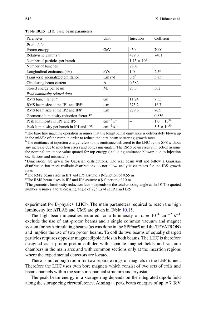
Table 10.15 LHC basic beam parameters
Parameter
Unit
Injection
Collision
Beam data
Proton energy
GeV
450
7000
Relativistic gamma γ
479.6
7461
Number of particles per bunch
1.15 × 10 11
Number of bunches
2808
Longitudinal emittance (4σ )
eVs
1.0
2.5 a
Transverse normalized emittance
μm rad
3.5 b
3.75
Circulating beam current
A
0.582
Stored energy per beam
MJ
23.3
362
Peak luminosity related data
RMS bunch length c
cm
11.24
7.55
RMS beam size at the IP1 and IP5 d
μm
375.2
16.7
RMS beam size at the IP2 and IP8 e
μm
279.6
70.9
Geometric luminosity reduction factor F f
–
0.836
Peak luminosity in IP1 and IP5
cm −2 s −1
–
1.0 × 10 34
Peak luminosity per bunch in IP1 and IP5
cm −2 s −1
–
3.5 × 10 30
a The base line machine operation assumes that the longitudinal emittance is deliberately blown up
in the middle of the ramp in order to reduce the intra beam scattering growth rates
b The emittance at injection energy refers to the emittance delivered to the LHC by the SPS without
any increase due to injection errors and optics mis-match. The RMS beam sizes at injection assume
the nominal emittance value quoted for top energy (including emittance blowup due to injection
oscillations and mismatch)
c Dimensions are given for Gaussian distributions. The real beam will not follow a Gaussian
distribution but more realistic distributions do not allow analytic estimates for the IBS growth
rates
d The RMS beam sizes in IP1 and IP5 assume a β-function of 0.55 m
e The RMS beam sizes in IP2 and IP8 assume a β-function of 10 m
f The geometric luminosity reduction factor depends on the total crossing angle at the IP. The quoted
number assumes a total crossing angle of 285 μrad in IR1 and IR5
experiment for B-physics, LHCb. The main parameters required to reach the high
luminosity for ATLAS and CMS are given in Table 10.15.
The high beam intensities required for a luminosity of L = 10 34 cm −2 s −1
exclude the use of anti-proton beams and a single common vacuum and magnet
system for both circulating beams (as was done in the SPPbarS and the TEVATRON)
and implies the use of two proton beams. To collide two beams of equally charged
particles requires opposite magnet dipole fields in both beams. The LHC is therefore
designed as a proton-proton collider with separate magnet fields and vacuum
chambers in the main arcs and with common sections only at the insertion regions
where the experimental detectors are located.
There is not enough room for two separate rings of magnets in the LEP tunnel.
Therefore the LHC uses twin bore magnets which consist of two sets of coils and
beam channels within the same mechanical structure and cryostat.
The peak beam energy in a storage ring depends on the integrated dipole field
along the storage ring circumference. Aiming at peak beam energies of up to 7 TeV