

8 Accelerator Engineering and Technology: Accelerator Technology
413
purpose each power converter in the LHC has a dedicated controls electronics which
is actually an embedded microcontroller-based computer capable of performing
full local state control, reference function generation and measurement acquisition
as well as running a digital current regulation loop. Reference functions are
synchronized using a timing network. Each digital controller is connected to a field
bus (WorldFIP) and the timing network is used to synchronise the cycles of all
segments of the field bus. The digital controller disciplines a phase-locked loop to
align its clock to the start of each WorldFIP cycle guaranteeing synchronism of the
references along the machine.
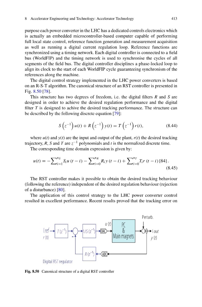
The digital control strategy implemented in the LHC power converters is based
on an R-S-T algorithm. The canonical structure of an RST controller is presented in
Fig. 8.50 [78].
This structure has two degrees of freedom, i.e. the digital filters R and S are
designed in order to achieve the desired regulation performance and the digital
filter T is designed to achive the desired tracking performance. The structure can
be described by the following discrete equation [79]:
S
z
−1
u(t) + R
z
−1
y(t) = T
z
−1
r(t),
(8.44)
where u(t) and y(t) are the input and output of the plant, r(t) the desired tracking
trajectory, R, S and T are z −1 polynomials and t is the normalized discrete time.
The corresponding time domain expression is given by:
u(t) = −
n S
i=1
S i u (t − i) −
n R
i=0
R i y (t − i) +
n T
i=0
T i r (t − i) [84] .
(8.45)
The RST controller makes it possible to obtain the desired tracking behaviour
(following the reference) independent of the desired regulation behaviour (rejection
of a disturbance) [80].
The application of this control strategy to the LHC power converter control
resulted in excellent performance. Recent results proved that the tracking error on
I out
ADC
DAC
I ref
-
Digital RST regulator
Perturb.
-
r (t)
y (t)
u (t)
T (z
–1
)
1/S (z
–1
)
R (z
–1
)
PC
&
Main magnets
Fig. 8.50 Canonical structure of a digital RST controller
413
purpose each power converter in the LHC has a dedicated controls electronics which
is actually an embedded microcontroller-based computer capable of performing
full local state control, reference function generation and measurement acquisition
as well as running a digital current regulation loop. Reference functions are
synchronized using a timing network. Each digital controller is connected to a field
bus (WorldFIP) and the timing network is used to synchronise the cycles of all
segments of the field bus. The digital controller disciplines a phase-locked loop to
align its clock to the start of each WorldFIP cycle guaranteeing synchronism of the
references along the machine.
The digital control strategy implemented in the LHC power converters is based
on an R-S-T algorithm. The canonical structure of an RST controller is presented in
Fig. 8.50 [78].
This structure has two degrees of freedom, i.e. the digital filters R and S are
designed in order to achieve the desired regulation performance and the digital
filter T is designed to achive the desired tracking performance. The structure can
be described by the following discrete equation [79]:
S
z
−1
u(t) + R
z
−1
y(t) = T
z
−1
r(t),
(8.44)
where u(t) and y(t) are the input and output of the plant, r(t) the desired tracking
trajectory, R, S and T are z −1 polynomials and t is the normalized discrete time.
The corresponding time domain expression is given by:
u(t) = −
n S
i=1
S i u (t − i) −
n R
i=0
R i y (t − i) +
n T
i=0
T i r (t − i) [84] .
(8.45)
The RST controller makes it possible to obtain the desired tracking behaviour
(following the reference) independent of the desired regulation behaviour (rejection
of a disturbance) [80].
The application of this control strategy to the LHC power converter control
resulted in excellent performance. Recent results proved that the tracking error on
I out
ADC
DAC
I ref
-
Digital RST regulator
Perturb.
-
r (t)
y (t)
u (t)
T (z
–1
)
1/S (z
–1
)
R (z
–1
)
PC
&
Main magnets
Fig. 8.50 Canonical structure of a digital RST controller