

2 Beam Dynamics
29
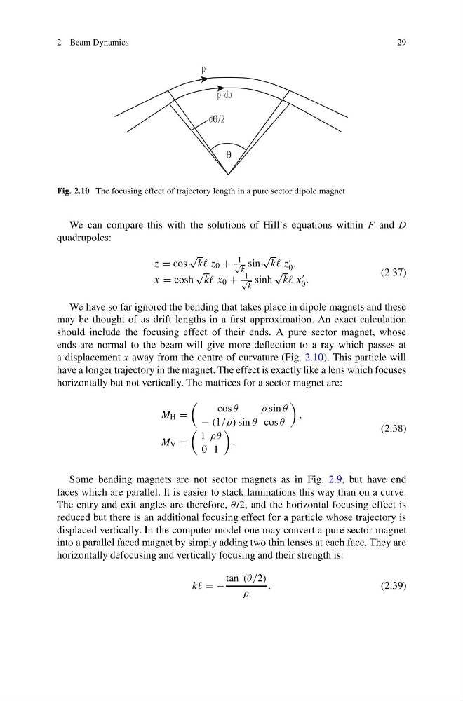
Fig. 2.10 The focusing effect of trajectory length in a pure sector dipole magnet
We can compare this with the solutions of Hill’s equations within F and D
quadrupoles:
z = cos
√
kk z 0 +
1
√
k
sin
√
kk z
0 ,
x = cosh
√
kk x 0 +
1
√
k
sinh
√
kk x
0 .
(2.37)
We have so far ignored the bending that takes place in dipole magnets and these
may be thought of as drift lengths in a first approximation. An exact calculation
should include the focusing effect of their ends. A pure sector magnet, whose
ends are normal to the beam will give more deflection to a ray which passes at
a displacement x away from the centre of curvature (Fig. 2.10). This particle will
have a longer trajectory in the magnet. The effect is exactly like a lens which focuses
horizontally but not vertically. The matrices for a sector magnet are:
M H =
cos θ
ρsin θ
− (1/ρ) sin θ cos θ
,
M V =
1 ρθ
0 1
.
(2.38)
Some bending magnets are not sector magnets as in Fig. 2.9, but have end
faces which are parallel. It is easier to stack laminations this way than on a curve.
The entry and exit angles are therefore, θ /2, and the horizontal focusing effect is
reduced but there is an additional focusing effect for a particle whose trajectory is
displaced vertically. In the computer model one may convert a pure sector magnet
into a parallel faced magnet by simply adding two thin lenses at each face. They are
horizontally defocusing and vertically focusing and their strength is:
kk = −
tan (θ/2)
ρ
.
(2.39)
29
Fig. 2.10 The focusing effect of trajectory length in a pure sector dipole magnet
We can compare this with the solutions of Hill’s equations within F and D
quadrupoles:
z = cos
√
kk z 0 +
1
√
k
sin
√
kk z
0 ,
x = cosh
√
kk x 0 +
1
√
k
sinh
√
kk x
0 .
(2.37)
We have so far ignored the bending that takes place in dipole magnets and these
may be thought of as drift lengths in a first approximation. An exact calculation
should include the focusing effect of their ends. A pure sector magnet, whose
ends are normal to the beam will give more deflection to a ray which passes at
a displacement x away from the centre of curvature (Fig. 2.10). This particle will
have a longer trajectory in the magnet. The effect is exactly like a lens which focuses
horizontally but not vertically. The matrices for a sector magnet are:
M H =
cos θ
ρsin θ
− (1/ρ) sin θ cos θ
,
M V =
1 ρθ
0 1
.
(2.38)
Some bending magnets are not sector magnets as in Fig. 2.9, but have end
faces which are parallel. It is easier to stack laminations this way than on a curve.
The entry and exit angles are therefore, θ /2, and the horizontal focusing effect is
reduced but there is an additional focusing effect for a particle whose trajectory is
displaced vertically. In the computer model one may convert a pure sector magnet
into a parallel faced magnet by simply adding two thin lenses at each face. They are
horizontally defocusing and vertically focusing and their strength is:
kk = −
tan (θ/2)
ρ
.
(2.39)