

314
J. Seeman et al.
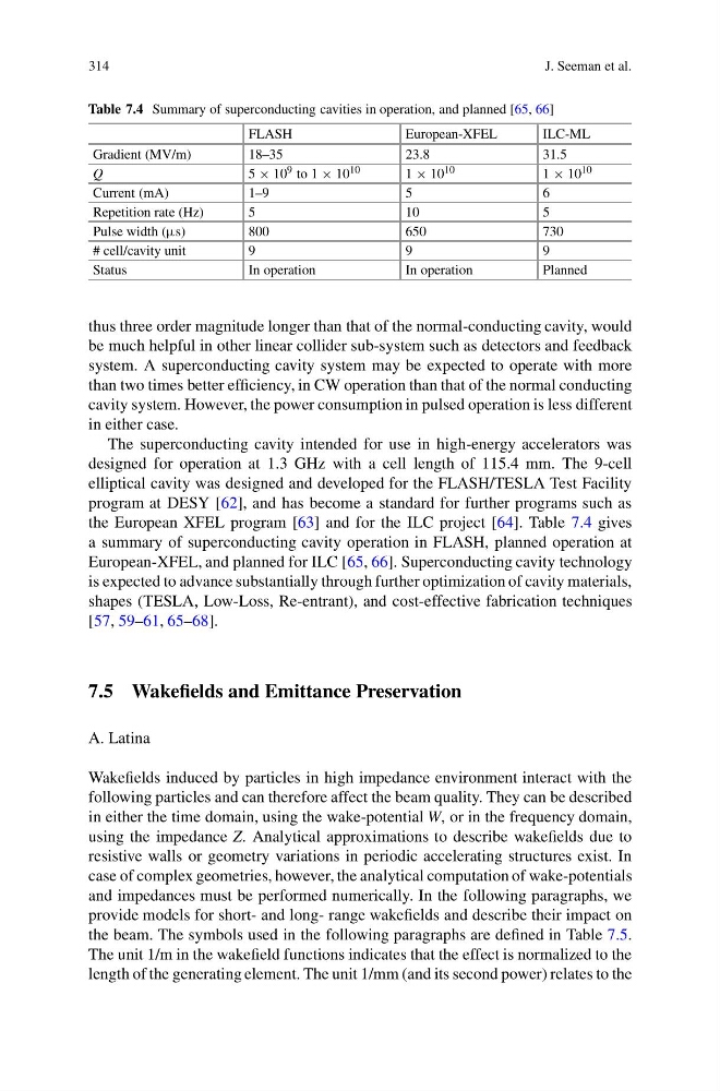
Table 7.4 Summary of superconducting cavities in operation, and planned [65, 66]
FLASH
European-XFEL
ILC-ML
Gradient (MV/m)
18–35
23.8
31.5
Q
5 × 10 9 to 1 × 10 10
1 × 10 10
1 × 10 10
Current (mA)
1–9
5
6
Repetition rate (Hz)
5
10
5
Pulse width (μs)
800
650
730
# cell/cavity unit
9
9
9
Status
In operation
In operation
Planned
thus three order magnitude longer than that of the normal-conducting cavity, would
be much helpful in other linear collider sub-system such as detectors and feedback
system. A superconducting cavity system may be expected to operate with more
than two times better efficiency, in CW operation than that of the normal conducting
cavity system. However, the power consumption in pulsed operation is less different
in either case.
The superconducting cavity intended for use in high-energy accelerators was
designed for operation at 1.3 GHz with a cell length of 115.4 mm. The 9-cell
elliptical cavity was designed and developed for the FLASH/TESLA Test Facility
program at DESY [62], and has become a standard for further programs such as
the European XFEL program [63] and for the ILC project [64]. Table 7.4 gives
a summary of superconducting cavity operation in FLASH, planned operation at
European-XFEL, and planned for ILC [65, 66]. Superconducting cavity technology
is expected to advance substantially through further optimization of cavity materials,
shapes (TESLA, Low-Loss, Re-entrant), and cost-effective fabrication techniques
[57, 59–61, 65–68].
7.5 Wakefields and Emittance Preservation
A. Latina
Wakefields induced by particles in high impedance environment interact with the
following particles and can therefore affect the beam quality. They can be described
in either the time domain, using the wake-potential W, or in the frequency domain,
using the impedance Z. Analytical approximations to describe wakefields due to
resistive walls or geometry variations in periodic accelerating structures exist. In
case of complex geometries, however, the analytical computation of wake-potentials
and impedances must be performed numerically. In the following paragraphs, we
provide models for short- and long- range wakefields and describe their impact on
the beam. The symbols used in the following paragraphs are defined in Table 7.5.
The unit 1/m in the wakefield functions indicates that the effect is normalized to the
length of the generating element. The unit 1/mm (and its second power) relates to the
J. Seeman et al.
Table 7.4 Summary of superconducting cavities in operation, and planned [65, 66]
FLASH
European-XFEL
ILC-ML
Gradient (MV/m)
18–35
23.8
31.5
Q
5 × 10 9 to 1 × 10 10
1 × 10 10
1 × 10 10
Current (mA)
1–9
5
6
Repetition rate (Hz)
5
10
5
Pulse width (μs)
800
650
730
# cell/cavity unit
9
9
9
Status
In operation
In operation
Planned
thus three order magnitude longer than that of the normal-conducting cavity, would
be much helpful in other linear collider sub-system such as detectors and feedback
system. A superconducting cavity system may be expected to operate with more
than two times better efficiency, in CW operation than that of the normal conducting
cavity system. However, the power consumption in pulsed operation is less different
in either case.
The superconducting cavity intended for use in high-energy accelerators was
designed for operation at 1.3 GHz with a cell length of 115.4 mm. The 9-cell
elliptical cavity was designed and developed for the FLASH/TESLA Test Facility
program at DESY [62], and has become a standard for further programs such as
the European XFEL program [63] and for the ILC project [64]. Table 7.4 gives
a summary of superconducting cavity operation in FLASH, planned operation at
European-XFEL, and planned for ILC [65, 66]. Superconducting cavity technology
is expected to advance substantially through further optimization of cavity materials,
shapes (TESLA, Low-Loss, Re-entrant), and cost-effective fabrication techniques
[57, 59–61, 65–68].
7.5 Wakefields and Emittance Preservation
A. Latina
Wakefields induced by particles in high impedance environment interact with the
following particles and can therefore affect the beam quality. They can be described
in either the time domain, using the wake-potential W, or in the frequency domain,
using the impedance Z. Analytical approximations to describe wakefields due to
resistive walls or geometry variations in periodic accelerating structures exist. In
case of complex geometries, however, the analytical computation of wake-potentials
and impedances must be performed numerically. In the following paragraphs, we
provide models for short- and long- range wakefields and describe their impact on
the beam. The symbols used in the following paragraphs are defined in Table 7.5.
The unit 1/m in the wakefield functions indicates that the effect is normalized to the
length of the generating element. The unit 1/mm (and its second power) relates to the