

296
J. Seeman et al.
wide range of particle beams have been accelerated with linacs including beams
of electrons, positrons, protons, antiprotons, and heavy ions. Linac parameter
possibilities include pulsed versus continuous wave, low and high beam powers, low
and high repetition rates, low transverse emittance beams, short bunches with small
energy spreads, and accelerated multiple bunches in a single pulse. The number of
linacs around the world has grown tremendously with thousands of linacs in present
use, many for medical therapy, in industry, and for research and development in
a broad spectrum of scientific fields. Researchers have developed accelerators for
scientific tools in their own right, being awarded several Nobel prizes. Moreover,
linacs and particle accelerators in general have enabled many discovery level science
experiments in related fields, resulting in many Nobel prizes as well.
In this chapter the various types, near term uses, and future directions of linacs
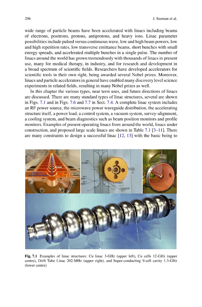
are discussed. There are many standard types of linac structures, several are shown
in Figs. 7.1 and in Figs. 7.6 and 7.7 in Sect. 7.4. A complete linac system includes
an RF power source, the microwave power waveguide distribution, the accelerating
structure itself, a power load, a control system, a vacuum system, survey-alignment,
a cooling system, and beam diagnostics such as beam position monitors and profile
monitors. Examples of present operating linacs from around the world, linacs under
construction, and proposed large scale linacs are shown in Table 7.1 [3–11]. There
are many constraints to design a successful linac [12, 13] with the basic being to
Fig. 7.1 Examples of linac structures: Cu linac 3-GHz (upper left), Cu cells 12-GHz (upper
centre), Drift Tube Linac 202-MHz (upper right), and Super-conducting 9-cell cavity 1.3-GHz
(lower centre)
J. Seeman et al.
wide range of particle beams have been accelerated with linacs including beams
of electrons, positrons, protons, antiprotons, and heavy ions. Linac parameter
possibilities include pulsed versus continuous wave, low and high beam powers, low
and high repetition rates, low transverse emittance beams, short bunches with small
energy spreads, and accelerated multiple bunches in a single pulse. The number of
linacs around the world has grown tremendously with thousands of linacs in present
use, many for medical therapy, in industry, and for research and development in
a broad spectrum of scientific fields. Researchers have developed accelerators for
scientific tools in their own right, being awarded several Nobel prizes. Moreover,
linacs and particle accelerators in general have enabled many discovery level science
experiments in related fields, resulting in many Nobel prizes as well.
In this chapter the various types, near term uses, and future directions of linacs
are discussed. There are many standard types of linac structures, several are shown
in Figs. 7.1 and in Figs. 7.6 and 7.7 in Sect. 7.4. A complete linac system includes
an RF power source, the microwave power waveguide distribution, the accelerating
structure itself, a power load, a control system, a vacuum system, survey-alignment,
a cooling system, and beam diagnostics such as beam position monitors and profile
monitors. Examples of present operating linacs from around the world, linacs under
construction, and proposed large scale linacs are shown in Table 7.1 [3–11]. There
are many constraints to design a successful linac [12, 13] with the basic being to
Fig. 7.1 Examples of linac structures: Cu linac 3-GHz (upper left), Cu cells 12-GHz (upper
centre), Drift Tube Linac 202-MHz (upper right), and Super-conducting 9-cell cavity 1.3-GHz
(lower centre)