

emission spectra which are hardly influenced by the physicochemical properties of
the host materials. This unique shielding effect imparts a weak electron–phonon
coupling and, thus, narrow-band emission resulting from electronic transitions.
Generally, direct excitation of RE ions is a relatively inefficient process due to the
forbidden character of the 4f transitions. The doping technique that involves the
introduction of a low concentration of ions (i.e., dopants) into an inorganic crystalline lattice (i.e., host) to obtain doped materials is widely employed to prepare
luminescent materials with intense emission. The RE dopants usually act as localized
optically active centers that emit at a specific wavelength when excited. These
dopants are further divided into sensitizers and activators in the case of sensitized
luminescence, where one dopant ion emits radiation from its high energetic state that
results from the energy transfer from another dopant ion, as shown in Fig. 10. The
dopant ion that gives out emission is described as an activator, while the ion that
donates energy to the activator is called the sensitizer. The absorption cross sections
of most RE activator ions are relatively low, resulting in low pump efficiency. Thus,
a sensitizer ion that exhibits a high absorption cross section is usually used as an
energy donor to the activator ion to enhance pump efficiency.
The mechanisms that govern the NIR-II emission originating from energy transfer within the 4f orbitals are broadly divided into two categories based on the
involved photon energy and the net number of photons, as shown in Fig. 11:
(1) down-conversion (DC) also known as quantum cutting and (2) down-shifting
(DS). The DC process refers to a process that involves generation of two or more
low-energy photons by splitting one absorbed high-energy photon. The DS process
describes a single photon process in which one incident higher-energy photon is
converted into one lower-energy photon.
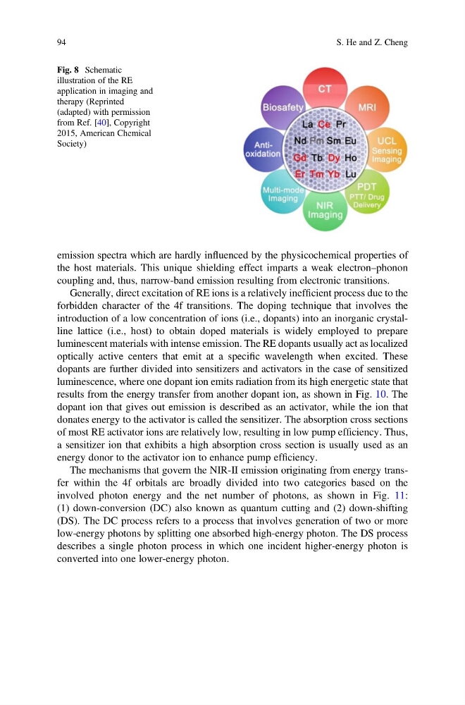
Fig. 8 Schematic
illustration of the RE
application in imaging and
therapy (Reprinted
(adapted) with permission
from Ref. [40], Copyright
2015, American Chemical
Society)
94
S. He and Z. Cheng
the host materials. This unique shielding effect imparts a weak electron–phonon
coupling and, thus, narrow-band emission resulting from electronic transitions.
Generally, direct excitation of RE ions is a relatively inefficient process due to the
forbidden character of the 4f transitions. The doping technique that involves the
introduction of a low concentration of ions (i.e., dopants) into an inorganic crystalline lattice (i.e., host) to obtain doped materials is widely employed to prepare
luminescent materials with intense emission. The RE dopants usually act as localized
optically active centers that emit at a specific wavelength when excited. These
dopants are further divided into sensitizers and activators in the case of sensitized
luminescence, where one dopant ion emits radiation from its high energetic state that
results from the energy transfer from another dopant ion, as shown in Fig. 10. The
dopant ion that gives out emission is described as an activator, while the ion that
donates energy to the activator is called the sensitizer. The absorption cross sections
of most RE activator ions are relatively low, resulting in low pump efficiency. Thus,
a sensitizer ion that exhibits a high absorption cross section is usually used as an
energy donor to the activator ion to enhance pump efficiency.
The mechanisms that govern the NIR-II emission originating from energy transfer within the 4f orbitals are broadly divided into two categories based on the
involved photon energy and the net number of photons, as shown in Fig. 11:
(1) down-conversion (DC) also known as quantum cutting and (2) down-shifting
(DS). The DC process refers to a process that involves generation of two or more
low-energy photons by splitting one absorbed high-energy photon. The DS process
describes a single photon process in which one incident higher-energy photon is
converted into one lower-energy photon.
Fig. 8 Schematic
illustration of the RE
application in imaging and
therapy (Reprinted
(adapted) with permission
from Ref. [40], Copyright
2015, American Chemical
Society)
94
S. He and Z. Cheng