

66
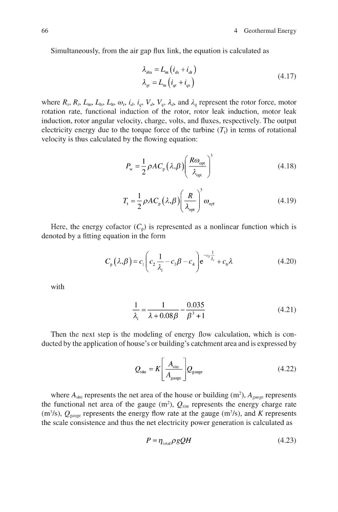
Simultaneously, from the air gap flux link, the equation is calculated as
O
O
d
d
d
q
q
q
L i i
L i i
m
m
s
r
r
m
r
s
(4.17)
where R s , R r , L m , L ls , L lr , ω r , i d , i q , V d , V q , λ d , and λ q represent the rotor force, motor
rotation rate, functional induction of the rotor, rotor leak induction, motor leak
induction, rotor angular velocity, charge, volts, and fluxes, respectively. The output
electricity energy due to the torque force of the turbine (T t ) in terms of rotational
velocity is thus calculated by the flowing equation:
P
AC
R
w
p
opt
opt
,
§
©
¨ ¨
·
¹
¸ ¸
1
2
3
U
OE
Z
O
(4.18)
T
AC
R
t
p
opt
opt
,
§
©
¨ ¨
·
¹
¸ ¸
1
2
3
U
OE O
Z
(4.19)
Here, the energy cofactor (C p ) is represented as a nonlinear function which is
denoted by a fitting equation in the form
C
c c
c
c
c
i
c
i
p
,
e
O E
O
E
O
O
§
©
¨
·
¹
¸
1
2
3
4
1
6
1
5
(4.20)
with
1
1
0 08
0 035
1
3
O O
E E
i
.
.
(4.21)
Then the next step is the modeling of energy flow calculation, which is conducted by the application of house’s or building’s catchment area and is expressed by
Q
K
A
A
Q
site
site
gauge
gauge
ª
¬
«
«
º
¼
»
»
(4.22)
where A site represents the net area of the house or building (m
2
), A gauge represents
the functional net area of the gauge (m
2
), Q site represents the energy charge rate
(m
3
/s), Q gauge represents the energy flow rate at the gauge (m
3
/s), and K represents
the scale consistence and thus the net electricity power generation is calculated as
P
g QH
K U
total
(4.23)
4 Geothermal Energy
Simultaneously, from the air gap flux link, the equation is calculated as
O
O
d
d
d
q
q
q
L i i
L i i
m
m
s
r
r
m
r
s
(4.17)
where R s , R r , L m , L ls , L lr , ω r , i d , i q , V d , V q , λ d , and λ q represent the rotor force, motor
rotation rate, functional induction of the rotor, rotor leak induction, motor leak
induction, rotor angular velocity, charge, volts, and fluxes, respectively. The output
electricity energy due to the torque force of the turbine (T t ) in terms of rotational
velocity is thus calculated by the flowing equation:
P
AC
R
w
p
opt
opt
,
§
©
¨ ¨
·
¹
¸ ¸
1
2
3
U
OE
Z
O
(4.18)
T
AC
R
t
p
opt
opt
,
§
©
¨ ¨
·
¹
¸ ¸
1
2
3
U
OE O
Z
(4.19)
Here, the energy cofactor (C p ) is represented as a nonlinear function which is
denoted by a fitting equation in the form
C
c c
c
c
c
i
c
i
p
,
e
O E
O
E
O
O
§
©
¨
·
¹
¸
1
2
3
4
1
6
1
5
(4.20)
with
1
1
0 08
0 035
1
3
O O
E E
i
.
.
(4.21)
Then the next step is the modeling of energy flow calculation, which is conducted by the application of house’s or building’s catchment area and is expressed by
Q
K
A
A
Q
site
site
gauge
gauge
ª
¬
«
«
º
¼
»
»
(4.22)
where A site represents the net area of the house or building (m
2
), A gauge represents
the functional net area of the gauge (m
2
), Q site represents the energy charge rate
(m
3
/s), Q gauge represents the energy flow rate at the gauge (m
3
/s), and K represents
the scale consistence and thus the net electricity power generation is calculated as
P
g QH
K U
total
(4.23)
4 Geothermal Energy