

63
J
T K
T
t t
a
t t
g
Z
Z
(4.2)
and
J J n J
K K n K
T n T
t
r
g g
t
r
g g
g
g em
2
2
(4.3)
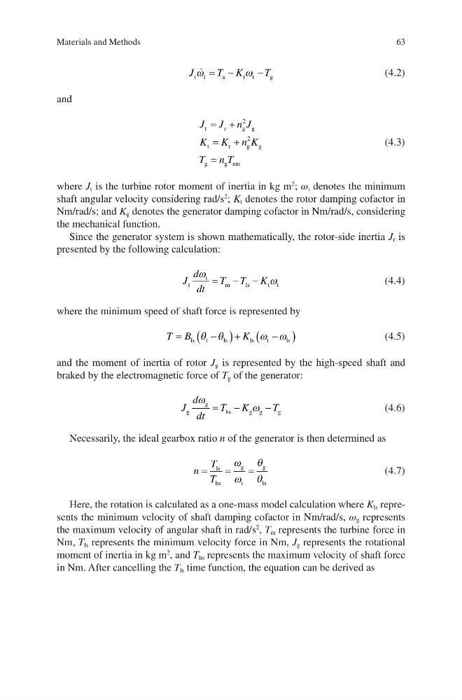
where J t is the turbine rotor moment of inertia in kg m
2
; ω t denotes the minimum
shaft angular velocity considering rad/s
2
; K t denotes the rotor damping cofactor in
Nm/rad/s; and K g denotes the generator damping cofactor in Nm/rad/s, considering
the mechanical function.
Since the generator system is shown mathematically, the rotor-side inertia J r is
presented by the following calculation:
J
d
dt
T T K
t
t
m
l s
t t
Z
Z
(4.4)
where the minimum speed of shaft force is represented by
T B
K
ls
t
l s
l s
t
ls
T T
Z Z
(4.5)
and the moment of inertia of rotor J g is represented by the high-speed shaft and
braked by the electromagnetic force of T g of the generator:
J
d
dt
T K
T
g
g
hs
g g
g
Z
Z
(4.6)
Necessarily, the ideal gearbox ratio n of the generator is then determined as
n
T
T
ls
hs
g
t
g
ls
Z
Z
T
T
(4.7)
Here, the rotation is calculated as a one-mass model calculation where K ls represents the minimum velocity of shaft damping cofactor in Nm/rad/s, ω g represents
the maximum velocity of angular shaft in rad/s
2
, T m represents the turbine force in
Nm, T ls represents the minimum velocity force in Nm, J g represents the rotational
moment of inertia in kg m
2
, and T hs represents the maximum velocity of shaft force
in Nm. After cancelling the T ls time function, the equation can be derived as
Materials and Methods
J
T K
T
t t
a
t t
g
Z
Z
(4.2)
and
J J n J
K K n K
T n T
t
r
g g
t
r
g g
g
g em
2
2
(4.3)
where J t is the turbine rotor moment of inertia in kg m
2
; ω t denotes the minimum
shaft angular velocity considering rad/s
2
; K t denotes the rotor damping cofactor in
Nm/rad/s; and K g denotes the generator damping cofactor in Nm/rad/s, considering
the mechanical function.
Since the generator system is shown mathematically, the rotor-side inertia J r is
presented by the following calculation:
J
d
dt
T T K
t
t
m
l s
t t
Z
Z
(4.4)
where the minimum speed of shaft force is represented by
T B
K
ls
t
l s
l s
t
ls
T T
Z Z
(4.5)
and the moment of inertia of rotor J g is represented by the high-speed shaft and
braked by the electromagnetic force of T g of the generator:
J
d
dt
T K
T
g
g
hs
g g
g
Z
Z
(4.6)
Necessarily, the ideal gearbox ratio n of the generator is then determined as
n
T
T
ls
hs
g
t
g
ls
Z
Z
T
T
(4.7)
Here, the rotation is calculated as a one-mass model calculation where K ls represents the minimum velocity of shaft damping cofactor in Nm/rad/s, ω g represents
the maximum velocity of angular shaft in rad/s
2
, T m represents the turbine force in
Nm, T ls represents the minimum velocity force in Nm, J g represents the rotational
moment of inertia in kg m
2
, and T hs represents the maximum velocity of shaft force
in Nm. After cancelling the T ls time function, the equation can be derived as
Materials and Methods