

189
The net realistic energy variants in the fuzzy controller are subsequently calculated from this fuzzy controller. Therefore, the net wind energy production is calculated by triangular, trapezoidal, and symmetrical speed functions of the wind turbine
generator. Simply the FLC of DFIG has been calculated by analyzing the net current
formation of the wind turbine and is expressed by
e n i n i n
e n i n i n
i
d
d
i
q
q
d
q
r
r
r
r
r
r
( ) = ( )− ( )
( ) = ( )− ( )
∗
∗
(10.29)
And again, the equation is simplified as
∆
∆
e n i n i n
e n i n i n
i
d
d
i
q
q
d
q
r
r
r
r
r
r
( ) = ( )−
−
( )
( ) = ( )−
−
( )
∗
∗
1
1
(10.30)
Finally, the input and output variables of wind energy conversion mechanism by
the fuzzy controller have been quantized and thus the wind energy transformation
rate is determined by the effect of wind speed in changing the output power into the
rotor of the wind turbine [2, 19]. Therefore, the changes in the output power in the
rotor while the vehicle is running are computed in order to have a trade-off between
accuracy and complexity of wind energy conversion through the rigorous simulation to produce desirable enteric energy for running the vehicle.
Electrical Subsystem Modeling
Once the wind energy modeling has been analyzed, the implementation of this wind
energy into the electrical subsystem is calculated to run the vehicle. Therefore, both
induction and synchronous wind energy driven by the rotor is captured by permanent magnet synchronous generator (PMSG) in order to convert it into electric
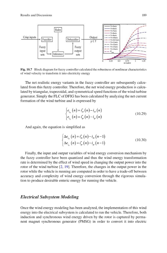
Fig. 10.7 Block diagram for fuzzy controller calculated the robustness of nonlinear characteristics
of wind velocity to transform it into electricity energy
Results and Discussions
The net realistic energy variants in the fuzzy controller are subsequently calculated from this fuzzy controller. Therefore, the net wind energy production is calculated by triangular, trapezoidal, and symmetrical speed functions of the wind turbine
generator. Simply the FLC of DFIG has been calculated by analyzing the net current
formation of the wind turbine and is expressed by
e n i n i n
e n i n i n
i
d
d
i
q
q
d
q
r
r
r
r
r
r
( ) = ( )− ( )
( ) = ( )− ( )
∗
∗
(10.29)
And again, the equation is simplified as
∆
∆
e n i n i n
e n i n i n
i
d
d
i
q
q
d
q
r
r
r
r
r
r
( ) = ( )−
−
( )
( ) = ( )−
−
( )
∗
∗
1
1
(10.30)
Finally, the input and output variables of wind energy conversion mechanism by
the fuzzy controller have been quantized and thus the wind energy transformation
rate is determined by the effect of wind speed in changing the output power into the
rotor of the wind turbine [2, 19]. Therefore, the changes in the output power in the
rotor while the vehicle is running are computed in order to have a trade-off between
accuracy and complexity of wind energy conversion through the rigorous simulation to produce desirable enteric energy for running the vehicle.
Electrical Subsystem Modeling
Once the wind energy modeling has been analyzed, the implementation of this wind
energy into the electrical subsystem is calculated to run the vehicle. Therefore, both
induction and synchronous wind energy driven by the rotor is captured by permanent magnet synchronous generator (PMSG) in order to convert it into electric
Fig. 10.7 Block diagram for fuzzy controller calculated the robustness of nonlinear characteristics
of wind velocity to transform it into electricity energy
Results and Discussions