

139
T T
G
c
a
t
NOCT
= +
−
20
800
(7.18)
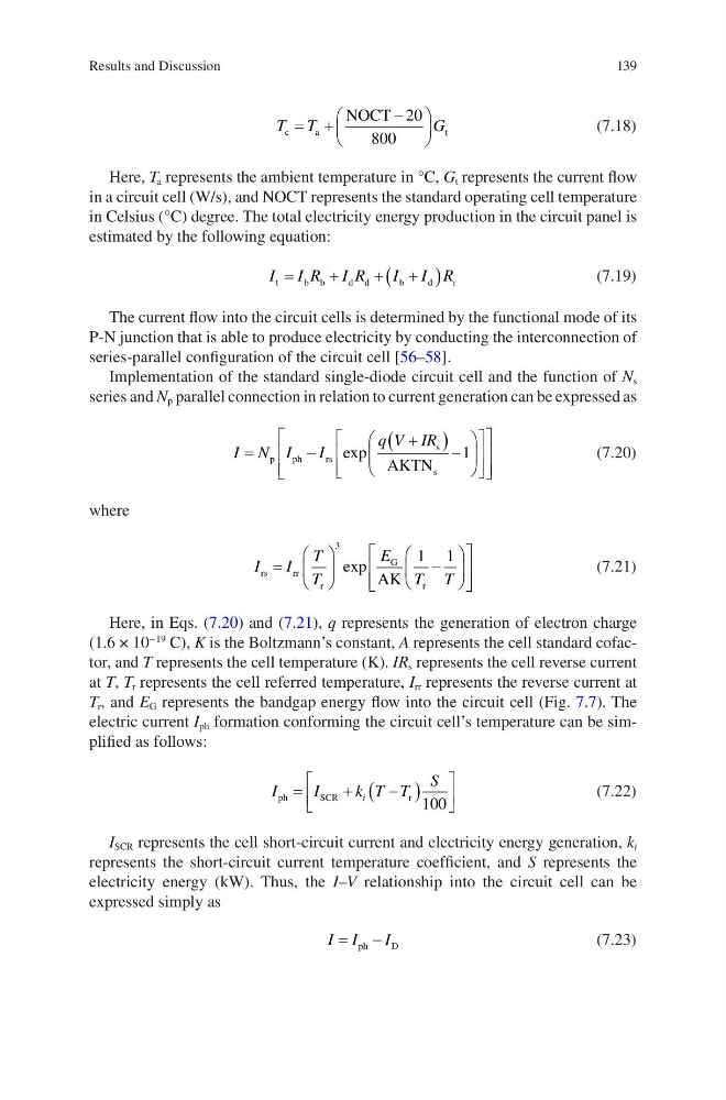
Here, T a represents the ambient temperature in °C, G t represents the current flow
in a circuit cell (W/s), and NOCT represents the standard operating cell temperature
in Celsius (°C) degree. The total electricity energy production in the circuit panel is
estimated by the following equation:
I I R I R
I I R
t
b b
d d
b
d
r
=
+
+
+
(
)
(7.19)
The current flow into the circuit cells is determined by the functional mode of its
P-N junction that is able to produce electricity by conducting the interconnection of
series-parallel configuration of the circuit cell [56–58].
Implementation of the standard single-diode circuit cell and the function of N s
series and N p parallel connection in relation to current generation can be expressed as
I N I
I
q V IR
=
−
+
(
) −
p
p h
r s
s
s
AKTN
exp
1
(7.20)
where
I
I
T
T
E
T T
rs
rr
r
G
r
AK
=
−
3
1 1
exp
(7.21)
Here, in Eqs. (7.20) and (7.21), q represents the generation of electron charge
(1.6 × 10
−19
C), K is the Boltzmann’s constant, A represents the cell standard cofactor, and T represents the cell temperature (K). IR s represents the cell reverse current
at T, T r represents the cell referred temperature, I rr represents the reverse current at
T r , and E G represents the bandgap energy flow into the circuit cell (Fig. 7.7). The
electric current I ph formation conforming the circuit cell’s temperature can be simplified as follows:
I
I
k T T
S
i
ph
SCR
r
=
+
−
(
)
100
(7.22)
I SCR represents the cell short-circuit current and electricity energy generation, k i
represents the short-circuit current temperature coefficient, and S represents the
electricity energy (kW). Thus, the I–V relationship into the circuit cell can be
expressed simply as
I I
I
=
−
ph
D
(7.23)
Results and Discussion
T T
G
c
a
t
NOCT
= +
−
20
800
(7.18)
Here, T a represents the ambient temperature in °C, G t represents the current flow
in a circuit cell (W/s), and NOCT represents the standard operating cell temperature
in Celsius (°C) degree. The total electricity energy production in the circuit panel is
estimated by the following equation:
I I R I R
I I R
t
b b
d d
b
d
r
=
+
+
+
(
)
(7.19)
The current flow into the circuit cells is determined by the functional mode of its
P-N junction that is able to produce electricity by conducting the interconnection of
series-parallel configuration of the circuit cell [56–58].
Implementation of the standard single-diode circuit cell and the function of N s
series and N p parallel connection in relation to current generation can be expressed as
I N I
I
q V IR
=
−
+
(
) −
p
p h
r s
s
s
AKTN
exp
1
(7.20)
where
I
I
T
T
E
T T
rs
rr
r
G
r
AK
=
−
3
1 1
exp
(7.21)
Here, in Eqs. (7.20) and (7.21), q represents the generation of electron charge
(1.6 × 10
−19
C), K is the Boltzmann’s constant, A represents the cell standard cofactor, and T represents the cell temperature (K). IR s represents the cell reverse current
at T, T r represents the cell referred temperature, I rr represents the reverse current at
T r , and E G represents the bandgap energy flow into the circuit cell (Fig. 7.7). The
electric current I ph formation conforming the circuit cell’s temperature can be simplified as follows:
I
I
k T T
S
i
ph
SCR
r
=
+
−
(
)
100
(7.22)
I SCR represents the cell short-circuit current and electricity energy generation, k i
represents the short-circuit current temperature coefficient, and S represents the
electricity energy (kW). Thus, the I–V relationship into the circuit cell can be
expressed simply as
I I
I
=
−
ph
D
(7.23)
Results and Discussion