

54
2 Methods for Investigating Electro-Chemo-Mechanical …
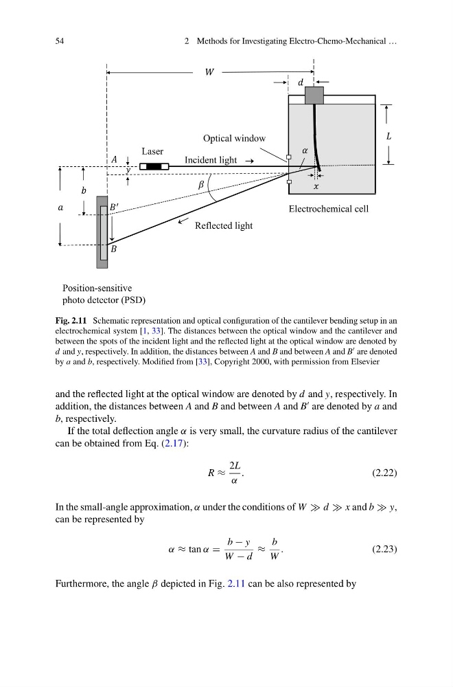
Fig. 2.11 Schematic representation and optical configuration of the cantilever bending setup in an
electrochemical system [1, 33]. The distances between the optical window and the cantilever and
between the spots of the incident light and the reflected light at the optical window are denoted by
d and y, respectively. In addition, the distances between A and B and between A and B are denoted
by a and b, respectively. Modified from [33], Copyright 2000, with permission from Elsevier
and the reflected light at the optical window are denoted by d and y, respectively. In
addition, the distances between A and B and between A and B
are denoted by a and
b, respectively.
If the total deflection angle α is very small, the curvature radius of the cantilever
can be obtained from Eq. (2.17):
R ≈
2L
α
.
(2.22)
In the small-angle approximation, α under the conditions of W d x and b y,
can be represented by
α ≈ tan α =
b − y
W − d
≈
b
W
.
(2.23)
Furthermore, the angle β depicted in Fig. 2.11 can be also represented by
2 Methods for Investigating Electro-Chemo-Mechanical …
Fig. 2.11 Schematic representation and optical configuration of the cantilever bending setup in an
electrochemical system [1, 33]. The distances between the optical window and the cantilever and
between the spots of the incident light and the reflected light at the optical window are denoted by
d and y, respectively. In addition, the distances between A and B and between A and B are denoted
by a and b, respectively. Modified from [33], Copyright 2000, with permission from Elsevier
and the reflected light at the optical window are denoted by d and y, respectively. In
addition, the distances between A and B and between A and B
are denoted by a and
b, respectively.
If the total deflection angle α is very small, the curvature radius of the cantilever
can be obtained from Eq. (2.17):
R ≈
2L
α
.
(2.22)
In the small-angle approximation, α under the conditions of W d x and b y,
can be represented by
α ≈ tan α =
b − y
W − d
≈
b
W
.
(2.23)
Furthermore, the angle β depicted in Fig. 2.11 can be also represented by