

52
2 Methods for Investigating Electro-Chemo-Mechanical …
L = 2R sin θ cos θ ≈ 2Rθ,
(2.16)
and
1
R
= κ ≈
2θ
L
=
α
2L
.
(2.17)
As the cantilever bends, the total deflection angle α increases to bring the changes
in the spot of the reflected light on a detector plane, from which the changes in
1
R
or
κ are calculated by using Eq. (2.17).
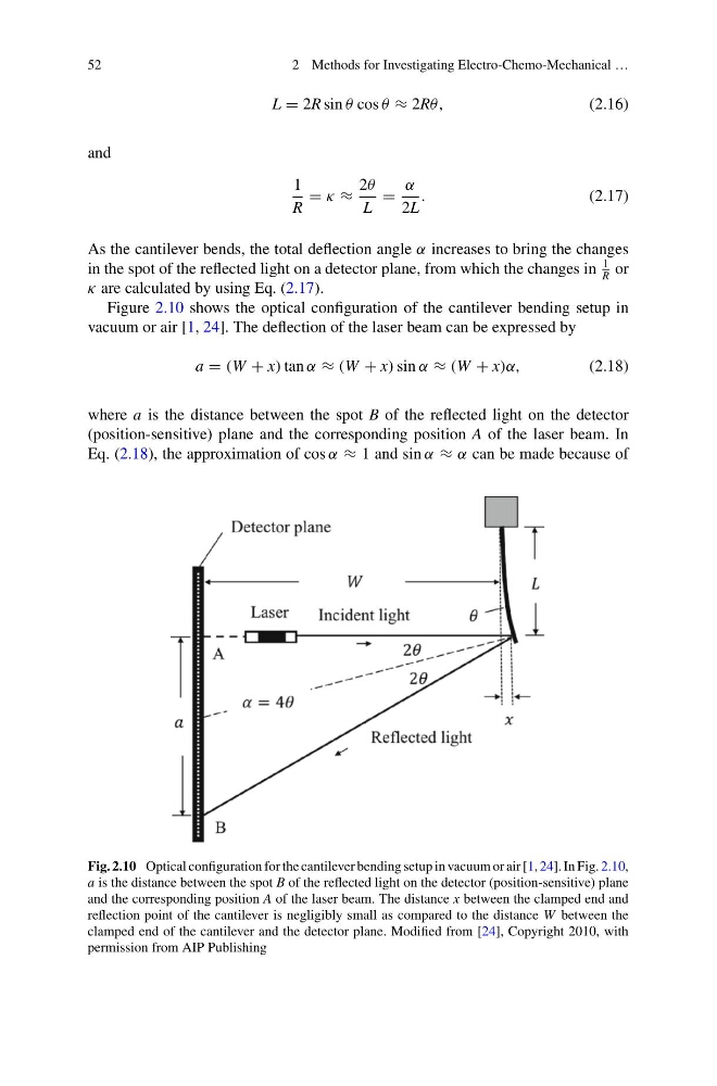
Figure 2.10 shows the optical configuration of the cantilever bending setup in
vacuum or air [1, 24]. The deflection of the laser beam can be expressed by
a = (W + x) tan α ≈ (W + x) sin α ≈ (W + x)α,
(2.18)
where a is the distance between the spot B of the reflected light on the detector
(position-sensitive) plane and the corresponding position A of the laser beam. In
Eq. (2.18), the approximation of cos α ≈ 1 and sin α ≈ α can be made because of
Fig. 2.10 Optical configuration for the cantilever bending setup in vacuum or air [1, 24]. In Fig. 2.10,
a is the distance between the spot B of the reflected light on the detector (position-sensitive) plane
and the corresponding position A of the laser beam. The distance x between the clamped end and
reflection point of the cantilever is negligibly small as compared to the distance W between the
clamped end of the cantilever and the detector plane. Modified from [24], Copyright 2010, with
permission from AIP Publishing
2 Methods for Investigating Electro-Chemo-Mechanical …
L = 2R sin θ cos θ ≈ 2Rθ,
(2.16)
and
1
R
= κ ≈
2θ
L
=
α
2L
.
(2.17)
As the cantilever bends, the total deflection angle α increases to bring the changes
in the spot of the reflected light on a detector plane, from which the changes in
1
R
or
κ are calculated by using Eq. (2.17).
Figure 2.10 shows the optical configuration of the cantilever bending setup in
vacuum or air [1, 24]. The deflection of the laser beam can be expressed by
a = (W + x) tan α ≈ (W + x) sin α ≈ (W + x)α,
(2.18)
where a is the distance between the spot B of the reflected light on the detector
(position-sensitive) plane and the corresponding position A of the laser beam. In
Eq. (2.18), the approximation of cos α ≈ 1 and sin α ≈ α can be made because of
Fig. 2.10 Optical configuration for the cantilever bending setup in vacuum or air [1, 24]. In Fig. 2.10,
a is the distance between the spot B of the reflected light on the detector (position-sensitive) plane
and the corresponding position A of the laser beam. The distance x between the clamped end and
reflection point of the cantilever is negligibly small as compared to the distance W between the
clamped end of the cantilever and the detector plane. Modified from [24], Copyright 2010, with
permission from AIP Publishing