

194
7 Nano-Mechanical Properties of Solid Surfaces Obtained …
160
140
120
100
80
H
2
/ GPa
2
20x10
-3
15
10
5
0
h
-1 / nm
-1
Eq. (7.13)
Indentation data for MgO
by Feng and Nix [27]
H o
2
= 9.27 GPa
h* = 91.0 nm
without G,max
G,max = 1.28 x 10
16 m
-2
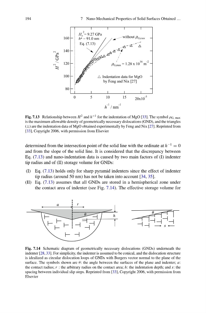
Fig. 7.13 Relationship between H 2 and h −1 for the indentation of MgO [33]. The symbol ρ G, max
is the maximum allowable density of geometrically necessary dislocations (GND), and the triangles
( are the indentation data of MgO obtained experimentally by Feng and Nix [27]. Reprinted from
[33], Copyright 2006, with permission from Elsevier
determined from the intersection point of the solid line with the ordinate at h
−1
= 0
and from the slope of the solid line. It is considered that the discrepancy between
Eq. (7.13) and nano-indentation data is caused by two main factors of (I) indenter
tip radius and of (II) storage volume for GNDs:
(I) Eq. (7.13) holds only for sharp pyramid indenters since the effect of indenter
tip radius (around 50 nm) has not be taken into account [34, 35].
(II) Eq. (7.13) assumes that all GNDs are stored in a hemispherical zone under
the contact area of indenter (see Fig. 7.14). The effective storage volume for
Fig. 7.14 Schematic diagram of geometrically necessary dislocations (GNDs) underneath the
indenter [28, 33]. For simplicity, the indenter is assumed to be conical, and the dislocation structure
is idealized as circular dislocation loops of GNDs with Burgers vector normal to the plane of the
surface. The symbols shown are θ: the angle between the surfaces of the plane and indenter; a:
the contact radius; r : the arbitrary radius on the contact area; h: the indentation depth; and s: the
spacing between individual slip steps. Reprinted from [33], Copyright 2006, with permission from
Elsevier
7 Nano-Mechanical Properties of Solid Surfaces Obtained …
160
140
120
100
80
H
2
/ GPa
2
20x10
-3
15
10
5
0
h
-1 / nm
-1
Eq. (7.13)
Indentation data for MgO
by Feng and Nix [27]
H o
2
= 9.27 GPa
h* = 91.0 nm
without G,max
G,max = 1.28 x 10
16 m
-2
Fig. 7.13 Relationship between H 2 and h −1 for the indentation of MgO [33]. The symbol ρ G, max
is the maximum allowable density of geometrically necessary dislocations (GND), and the triangles
( are the indentation data of MgO obtained experimentally by Feng and Nix [27]. Reprinted from
[33], Copyright 2006, with permission from Elsevier
determined from the intersection point of the solid line with the ordinate at h
−1
= 0
and from the slope of the solid line. It is considered that the discrepancy between
Eq. (7.13) and nano-indentation data is caused by two main factors of (I) indenter
tip radius and of (II) storage volume for GNDs:
(I) Eq. (7.13) holds only for sharp pyramid indenters since the effect of indenter
tip radius (around 50 nm) has not be taken into account [34, 35].
(II) Eq. (7.13) assumes that all GNDs are stored in a hemispherical zone under
the contact area of indenter (see Fig. 7.14). The effective storage volume for
Fig. 7.14 Schematic diagram of geometrically necessary dislocations (GNDs) underneath the
indenter [28, 33]. For simplicity, the indenter is assumed to be conical, and the dislocation structure
is idealized as circular dislocation loops of GNDs with Burgers vector normal to the plane of the
surface. The symbols shown are θ: the angle between the surfaces of the plane and indenter; a:
the contact radius; r : the arbitrary radius on the contact area; h: the indentation depth; and s: the
spacing between individual slip steps. Reprinted from [33], Copyright 2006, with permission from
Elsevier