

6.7 Residual Stress of Substrate Metal
169
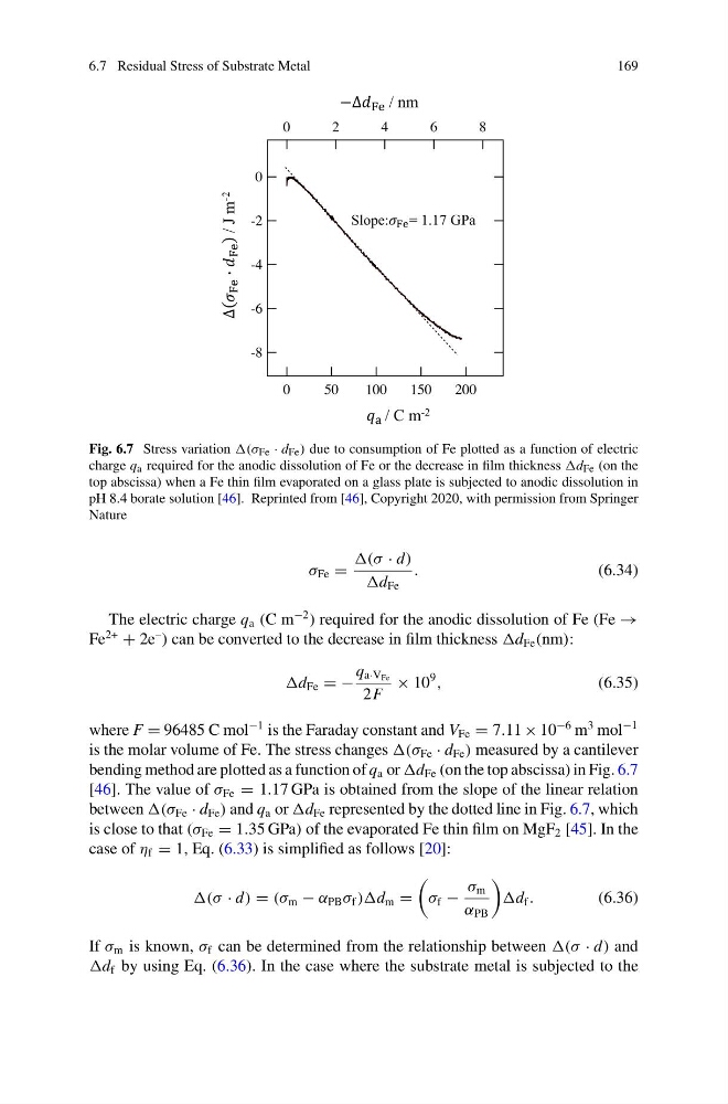
Fig. 6.7 Stress variation (σ Fe · d Fe ) due to consumption of Fe plotted as a function of electric
charge q a required for the anodic dissolution of Fe or the decrease in film thickness Fe (on the
top abscissa) when a Fe thin film evaporated on a glass plate is subjected to anodic dissolution in
pH 8.4 borate solution [46]. Reprinted from [46], Copyright 2020, with permission from Springer
Nature
σ Fe =
(σ · d)
d Fe
.
(6.34)
The electric charge q a (C m
−2 ) required for the anodic dissolution of Fe (Fe →
Fe
2+
+ 2e
– ) can be converted to the decrease in film thickness Fe (nm):
Fe = −
q a·V Fe
2F
× 10
9
,
(6.35)
where F = 96485 C mol
−1 is the Faraday constant and V Fe = 7.11 × 10
−6 m
3 mol
−1
is the molar volume of Fe. The stress changes (σ Fe · d Fe ) measured by a cantilever
bending method are plotted as a function of q a or Fe (on the top abscissa) in Fig. 6.7
[46]. The value of σ Fe = 1.17 GPa is obtained from the slope of the linear relation
between (σ Fe · d Fe ) and q a or Fe represented by the dotted line in Fig. 6.7, which
is close to that (σ Fe = 1.35 GPa) of the evaporated Fe thin film on MgF 2 [45]. In the
case of η f = 1, Eq. (6.33) is simplified as follows [20]:
(σ · d) = (σ m − α PB σ f ) m =
σ f −
σ m
α PB
f .
(6.36)
If σ m is known, σ f can be determined from the relationship between (σ · d) and
f by using Eq. (6.36). In the case where the substrate metal is subjected to the
169
Fig. 6.7 Stress variation (σ Fe · d Fe ) due to consumption of Fe plotted as a function of electric
charge q a required for the anodic dissolution of Fe or the decrease in film thickness Fe (on the
top abscissa) when a Fe thin film evaporated on a glass plate is subjected to anodic dissolution in
pH 8.4 borate solution [46]. Reprinted from [46], Copyright 2020, with permission from Springer
Nature
σ Fe =
(σ · d)
d Fe
.
(6.34)
The electric charge q a (C m
−2 ) required for the anodic dissolution of Fe (Fe →
Fe
2+
+ 2e
– ) can be converted to the decrease in film thickness Fe (nm):
Fe = −
q a·V Fe
2F
× 10
9
,
(6.35)
where F = 96485 C mol
−1 is the Faraday constant and V Fe = 7.11 × 10
−6 m
3 mol
−1
is the molar volume of Fe. The stress changes (σ Fe · d Fe ) measured by a cantilever
bending method are plotted as a function of q a or Fe (on the top abscissa) in Fig. 6.7
[46]. The value of σ Fe = 1.17 GPa is obtained from the slope of the linear relation
between (σ Fe · d Fe ) and q a or Fe represented by the dotted line in Fig. 6.7, which
is close to that (σ Fe = 1.35 GPa) of the evaporated Fe thin film on MgF 2 [45]. In the
case of η f = 1, Eq. (6.33) is simplified as follows [20]:
(σ · d) = (σ m − α PB σ f ) m =
σ f −
σ m
α PB
f .
(6.36)
If σ m is known, σ f can be determined from the relationship between (σ · d) and
f by using Eq. (6.36). In the case where the substrate metal is subjected to the