

5.8 Isentropic Processes and Carnot Cycles
A Carnot gas cycle’s four steps cyclic processes 1 ! 2 ! 3 ! 4 ! 1 are plotted
in the p-V diagram as shown in Fig. 4.4. The reversible adiabatic steps of 2 ! 3
and 4 ! 1 correspond to constant entropy steps according to Eq. (62) called
isentropic steps or processes. In Fig. 4.4, p and V variations of the isentropic steps
are related according to Eq. (70), or Eq. (41).
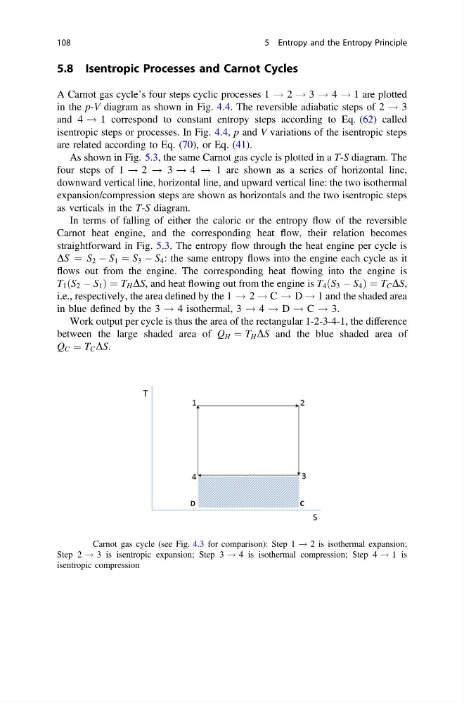
As shown in Fig. 5.3, the same Carnot gas cycle is plotted in a T-S diagram. The
four steps of 1 ! 2 ! 3 ! 4 ! 1 are shown as a series of horizontal line,
downward vertical line, horizontal line, and upward vertical line: the two isothermal
expansion/compression steps are shown as horizontals and the two isentropic steps
as verticals in the T-S diagram.
In terms of falling of either the caloric or the entropy flow of the reversible
Carnot heat engine, and the corresponding heat flow, their relation becomes
straightforward in Fig. 5.3. The entropy flow through the heat engine per cycle is
DS ¼ S 2 À S 1 ¼ S 3 À S 4 : the same entropy flows into the engine each cycle as it
flows out from the engine. The corresponding heat flowing into the engine is
T 1 S 2 À S 1
ð
Þ¼T H DS, and heat flowing out from the engine is T 4 S 3 À S 4
ð
Þ¼T C DS,
i.e., respectively, the area defined by the 1 ! 2 ! C ! D ! 1 and the shaded area
in blue defined by the 3 ! 4 isothermal, 3 ! 4 ! D ! C ! 3.
Work output per cycle is thus the area of the rectangular 1-2-3-4-1, the difference
between the large shaded area of Q H ¼ T H DS and the blue shaded area of
Q C ¼ T C DS.
S
T
D
C
Fig. 5.3 Carnot gas cycle (see Fig. 4.3 for comparison): Step 1 ! 2 is isothermal expansion;
Step 2 ! 3 is isentropic expansion; Step 3 ! 4 is isothermal compression; Step 4 ! 1 is
isentropic compression
108
5 Entropy and the Entropy Principle
A Carnot gas cycle’s four steps cyclic processes 1 ! 2 ! 3 ! 4 ! 1 are plotted
in the p-V diagram as shown in Fig. 4.4. The reversible adiabatic steps of 2 ! 3
and 4 ! 1 correspond to constant entropy steps according to Eq. (62) called
isentropic steps or processes. In Fig. 4.4, p and V variations of the isentropic steps
are related according to Eq. (70), or Eq. (41).
As shown in Fig. 5.3, the same Carnot gas cycle is plotted in a T-S diagram. The
four steps of 1 ! 2 ! 3 ! 4 ! 1 are shown as a series of horizontal line,
downward vertical line, horizontal line, and upward vertical line: the two isothermal
expansion/compression steps are shown as horizontals and the two isentropic steps
as verticals in the T-S diagram.
In terms of falling of either the caloric or the entropy flow of the reversible
Carnot heat engine, and the corresponding heat flow, their relation becomes
straightforward in Fig. 5.3. The entropy flow through the heat engine per cycle is
DS ¼ S 2 À S 1 ¼ S 3 À S 4 : the same entropy flows into the engine each cycle as it
flows out from the engine. The corresponding heat flowing into the engine is
T 1 S 2 À S 1
ð
Þ¼T H DS, and heat flowing out from the engine is T 4 S 3 À S 4
ð
Þ¼T C DS,
i.e., respectively, the area defined by the 1 ! 2 ! C ! D ! 1 and the shaded area
in blue defined by the 3 ! 4 isothermal, 3 ! 4 ! D ! C ! 3.
Work output per cycle is thus the area of the rectangular 1-2-3-4-1, the difference
between the large shaded area of Q H ¼ T H DS and the blue shaded area of
Q C ¼ T C DS.
S
T
D
C
Fig. 5.3 Carnot gas cycle (see Fig. 4.3 for comparison): Step 1 ! 2 is isothermal expansion;
Step 2 ! 3 is isentropic expansion; Step 3 ! 4 is isothermal compression; Step 4 ! 1 is
isentropic compression
108
5 Entropy and the Entropy Principle