

80
5 Mechanical characterization on structural element level
Model description
The virtual testing framework is based on a realistic representation of the experimental
bending setup. This means, that the implemented model includes the load and support
cylinders and the load is applied via contact formulations to the sandwich beam. Such
model setup enables to consider local indentation of the core as well as stress concentrations in the face sheet within the contact area. Analogous to the test, the load cylinders are prescribed with a translatory vertical constant velocity v, while the remaining
five DOF are constrained. The support cylinders are constrained in all six DOF. The contact between face sheet and cylinders is implemented as standard penalty contact with
a friction coefficient of 0.2. In order to reduce computational effort, symmetry of the
specimen and loading condition are utilized where applicable. In case of the four-point
bending setups, two symmetry planes are implemented leading to a quarter model (Figure 61 a). In case of the three-point bending setup, the single load cylinder is located in
the center of the beam. Therefore, only one symmetry plane along the longitudinal axis
(x-z plane) is implemented in order to limit interference of the symmetry boundary conditions with the core cell wall folding due to local indentation beneath the load cylinder
(Figure 61 b). In case of the four-point bending setup with additional loading plates, the
loading plates are represented by 3D-continuum elements (Figure 61 c), while the contact formulation is adopted from the face-cylinder contact. The element and material
modelling are adopted from the previous constituent level. The face sheets are modelled
using S4R elements and the built-in user subroutine for fabric reinforced composites (see
section 4.2.2). An element size of 2.0 mm is determined via convergence studies. The
shell thickness is modelled based on the nominal face sheet thickness. The fillet layer
(see Figure 57) is therefore physically neglected and its mechanical contribution is
smeared into the face sheet. The face sheet properties are derived from the constituent
level with the exception of the compressive strength, which was calibrated using the
bending tests. The core is modelled as determined on constituent level using two approaches. As meso-scale model it is modelled using S4R elements (element size 0.4 mm)
with accurate cell wall representation and with a single layer orthotropic-plastic material
model (for material properties see Table 10 on p. 51). In addition, the core is implemented with C3D8R elements using the previously implemented macroscopic orthotropic elasto-plastic material model (section 4.1.4).
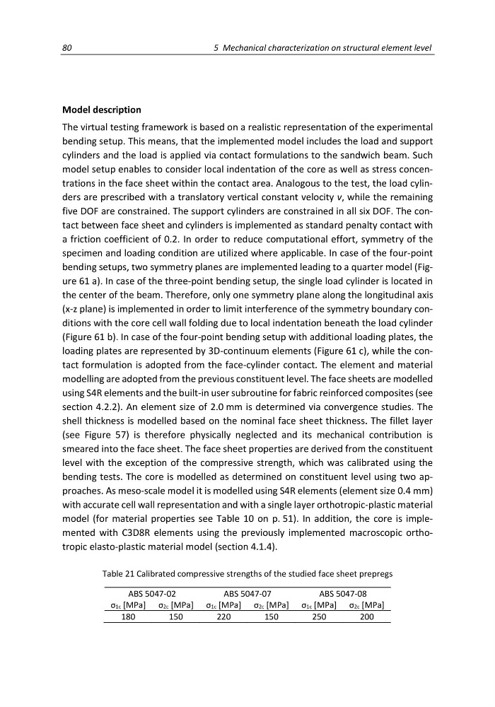
Table 21 Calibrated compressive strengths of the studied face sheet prepregs
ABS 5047-02
ABS 5047-07
ABS 5047-08
σ1c [MPa] σ2c [MPa] σ1c [MPa] σ2c [MPa] σ1c [MPa] σ2c [MPa]
180
150
220
150
250
200
5 Mechanical characterization on structural element level
Model description
The virtual testing framework is based on a realistic representation of the experimental
bending setup. This means, that the implemented model includes the load and support
cylinders and the load is applied via contact formulations to the sandwich beam. Such
model setup enables to consider local indentation of the core as well as stress concentrations in the face sheet within the contact area. Analogous to the test, the load cylinders are prescribed with a translatory vertical constant velocity v, while the remaining
five DOF are constrained. The support cylinders are constrained in all six DOF. The contact between face sheet and cylinders is implemented as standard penalty contact with
a friction coefficient of 0.2. In order to reduce computational effort, symmetry of the
specimen and loading condition are utilized where applicable. In case of the four-point
bending setups, two symmetry planes are implemented leading to a quarter model (Figure 61 a). In case of the three-point bending setup, the single load cylinder is located in
the center of the beam. Therefore, only one symmetry plane along the longitudinal axis
(x-z plane) is implemented in order to limit interference of the symmetry boundary conditions with the core cell wall folding due to local indentation beneath the load cylinder
(Figure 61 b). In case of the four-point bending setup with additional loading plates, the
loading plates are represented by 3D-continuum elements (Figure 61 c), while the contact formulation is adopted from the face-cylinder contact. The element and material
modelling are adopted from the previous constituent level. The face sheets are modelled
using S4R elements and the built-in user subroutine for fabric reinforced composites (see
section 4.2.2). An element size of 2.0 mm is determined via convergence studies. The
shell thickness is modelled based on the nominal face sheet thickness. The fillet layer
(see Figure 57) is therefore physically neglected and its mechanical contribution is
smeared into the face sheet. The face sheet properties are derived from the constituent
level with the exception of the compressive strength, which was calibrated using the
bending tests. The core is modelled as determined on constituent level using two approaches. As meso-scale model it is modelled using S4R elements (element size 0.4 mm)
with accurate cell wall representation and with a single layer orthotropic-plastic material
model (for material properties see Table 10 on p. 51). In addition, the core is implemented with C3D8R elements using the previously implemented macroscopic orthotropic elasto-plastic material model (section 4.1.4).
Table 21 Calibrated compressive strengths of the studied face sheet prepregs
ABS 5047-02
ABS 5047-07
ABS 5047-08
σ1c [MPa] σ2c [MPa] σ1c [MPa] σ2c [MPa] σ1c [MPa] σ2c [MPa]
180
150
220
150
250
200