

2.2 Sandwich structure joints
15
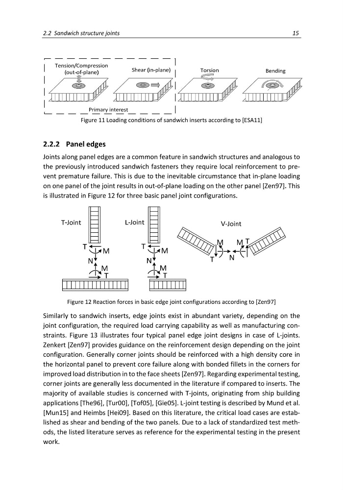
Figure 11 Loading conditions of sandwich inserts according to [ESA11]
2.2.2 Panel edges
Joints along panel edges are a common feature in sandwich structures and analogous to
the previously introduced sandwich fasteners they require local reinforcement to prevent premature failure. This is due to the inevitable circumstance that in-plane loading
on one panel of the joint results in out-of-plane loading on the other panel [Zen97]. This
is illustrated in Figure 12 for three basic panel joint configurations.
Figure 12 Reaction forces in basic edge joint configurations according to [Zen97]
Similarly to sandwich inserts, edge joints exist in abundant variety, depending on the
joint configuration, the required load carrying capability as well as manufacturing constraints. Figure 13 illustrates four typical panel edge joint designs in case of L-joints.
Zenkert [Zen97] provides guidance on the reinforcement design depending on the joint
configuration. Generally corner joints should be reinforced with a high density core in
the horizontal panel to prevent core failure along with bonded fillets in the corners for
improved load distribution in to the face sheets [Zen97]. Regarding experimental testing,
corner joints are generally less documented in the literature if compared to inserts. The
majority of available studies is concerned with T-joints, originating from ship building
applications [The96], [Tur00], [Tof05], [Gie05]. L-joint testing is described by Mund et al.
[Mun15] and Heimbs [Hei09]. Based on this literature, the critical load cases are established as shear and bending of the two panels. Due to a lack of standardized test methods, the listed literature serves as reference for the experimental testing in the present
work.
15
Figure 11 Loading conditions of sandwich inserts according to [ESA11]
2.2.2 Panel edges
Joints along panel edges are a common feature in sandwich structures and analogous to
the previously introduced sandwich fasteners they require local reinforcement to prevent premature failure. This is due to the inevitable circumstance that in-plane loading
on one panel of the joint results in out-of-plane loading on the other panel [Zen97]. This
is illustrated in Figure 12 for three basic panel joint configurations.
Figure 12 Reaction forces in basic edge joint configurations according to [Zen97]
Similarly to sandwich inserts, edge joints exist in abundant variety, depending on the
joint configuration, the required load carrying capability as well as manufacturing constraints. Figure 13 illustrates four typical panel edge joint designs in case of L-joints.
Zenkert [Zen97] provides guidance on the reinforcement design depending on the joint
configuration. Generally corner joints should be reinforced with a high density core in
the horizontal panel to prevent core failure along with bonded fillets in the corners for
improved load distribution in to the face sheets [Zen97]. Regarding experimental testing,
corner joints are generally less documented in the literature if compared to inserts. The
majority of available studies is concerned with T-joints, originating from ship building
applications [The96], [Tur00], [Tof05], [Gie05]. L-joint testing is described by Mund et al.
[Mun15] and Heimbs [Hei09]. Based on this literature, the critical load cases are established as shear and bending of the two panels. Due to a lack of standardized test methods, the listed literature serves as reference for the experimental testing in the present
work.