

184
Appendix A – Constituent level
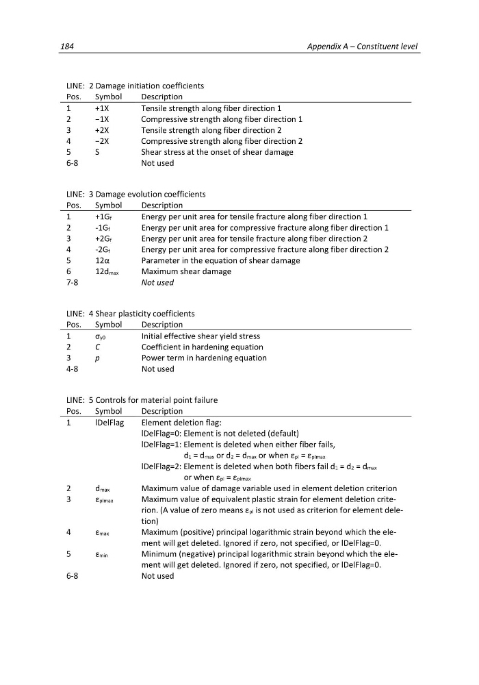
LINE: 2 Damage initiation coefficients
Pos.
Symbol
Description
1
+1X
Tensile strength along fiber direction 1
2
−1X
Compressive strength along fiber direction 1
3
+2X
Tensile strength along fiber direction 2
4
−2X
Compressive strength along fiber direction 2
5
S
Shear stress at the onset of shear damage
6-8
Not used
LINE: 3 Damage evolution coefficients
Pos.
Symbol
Description
1
+1Gf
Energy per unit area for tensile fracture along fiber direction 1
2
-1Gf
Energy per unit area for compressive fracture along fiber direction 1
3
+2Gf
Energy per unit area for tensile fracture along fiber direction 2
4
-2Gf
Energy per unit area for compressive fracture along fiber direction 2
5
12α
Parameter in the equation of shear damage
6
12dmax
Maximum shear damage
7-8
Not used
LINE: 4 Shear plasticity coefficients
Pos.
Symbol
Description
1
σy0
Initial effective shear yield stress
2
C
Coefficient in hardening equation
3
p
Power term in hardening equation
4-8
Not used
LINE: 5 Controls for material point failure
Pos.
Symbol
Description
1
lDelFlag
Element deletion flag:
lDelFlag=0: Element is not deleted (default)
lDelFlag=1: Element is deleted when either fiber fails,
d1 = dmax or d2 = dmax or when εpl = εplmax
lDelFlag=2: Element is deleted when both fibers fail d1 = d2 = dmax
or when εpl = εplmax
2
dmax
Maximum value of damage variable used in element deletion criterion
3
εplmax
Maximum value of equivalent plastic strain for element deletion criterion. (A value of zero means εpl is not used as criterion for element deletion)
4
εmax
Maximum (positive) principal logarithmic strain beyond which the element will get deleted. Ignored if zero, not specified, or lDelFlag=0.
5
εmin
Minimum (negative) principal logarithmic strain beyond which the element will get deleted. Ignored if zero, not specified, or lDelFlag=0.
6-8
Not used
Appendix A – Constituent level
LINE: 2 Damage initiation coefficients
Pos.
Symbol
Description
1
+1X
Tensile strength along fiber direction 1
2
−1X
Compressive strength along fiber direction 1
3
+2X
Tensile strength along fiber direction 2
4
−2X
Compressive strength along fiber direction 2
5
S
Shear stress at the onset of shear damage
6-8
Not used
LINE: 3 Damage evolution coefficients
Pos.
Symbol
Description
1
+1Gf
Energy per unit area for tensile fracture along fiber direction 1
2
-1Gf
Energy per unit area for compressive fracture along fiber direction 1
3
+2Gf
Energy per unit area for tensile fracture along fiber direction 2
4
-2Gf
Energy per unit area for compressive fracture along fiber direction 2
5
12α
Parameter in the equation of shear damage
6
12dmax
Maximum shear damage
7-8
Not used
LINE: 4 Shear plasticity coefficients
Pos.
Symbol
Description
1
σy0
Initial effective shear yield stress
2
C
Coefficient in hardening equation
3
p
Power term in hardening equation
4-8
Not used
LINE: 5 Controls for material point failure
Pos.
Symbol
Description
1
lDelFlag
Element deletion flag:
lDelFlag=0: Element is not deleted (default)
lDelFlag=1: Element is deleted when either fiber fails,
d1 = dmax or d2 = dmax or when εpl = εplmax
lDelFlag=2: Element is deleted when both fibers fail d1 = d2 = dmax
or when εpl = εplmax
2
dmax
Maximum value of damage variable used in element deletion criterion
3
εplmax
Maximum value of equivalent plastic strain for element deletion criterion. (A value of zero means εpl is not used as criterion for element deletion)
4
εmax
Maximum (positive) principal logarithmic strain beyond which the element will get deleted. Ignored if zero, not specified, or lDelFlag=0.
5
εmin
Minimum (negative) principal logarithmic strain beyond which the element will get deleted. Ignored if zero, not specified, or lDelFlag=0.
6-8
Not used