

7.7 Validation based on different joint configurations
145
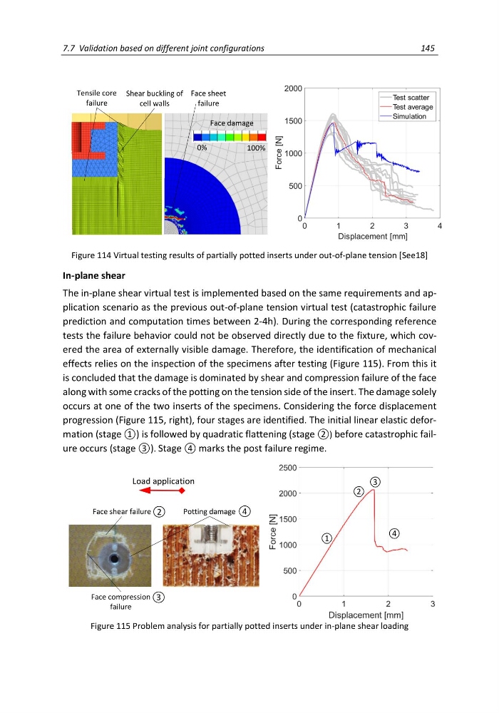
Figure 114 Virtual testing results of partially potted inserts under out-of-plane tension [See18]
In-plane shear
The in-plane shear virtual test is implemented based on the same requirements and application scenario as the previous out-of-plane tension virtual test (catastrophic failure
prediction and computation times between 2-4h). During the corresponding reference
tests the failure behavior could not be observed directly due to the fixture, which covered the area of externally visible damage. Therefore, the identification of mechanical
effects relies on the inspection of the specimens after testing (Figure 115). From this it
is concluded that the damage is dominated by shear and compression failure of the face
along with some cracks of the potting on the tension side of the insert. The damage solely
occurs at one of the two inserts of the specimens. Considering the force displacement
progression (Figure 115, right), four stages are identified. The initial linear elastic deformation (stage ①) is followed by quadratic flattening (stage ②) before catastrophic failure occurs (stage ③). Stage ④ marks the post failure regime.
Figure 115 Problem analysis for partially potted inserts under in-plane shear loading
Face damage
100%
0%
Shear buckling of
cell walls
Tensile core
failure
Face sheet
failure
Face shear failure
Face compression
failure
Potting damage 4
2
3
Load application
1
2
3
4
145
Figure 114 Virtual testing results of partially potted inserts under out-of-plane tension [See18]
In-plane shear
The in-plane shear virtual test is implemented based on the same requirements and application scenario as the previous out-of-plane tension virtual test (catastrophic failure
prediction and computation times between 2-4h). During the corresponding reference
tests the failure behavior could not be observed directly due to the fixture, which covered the area of externally visible damage. Therefore, the identification of mechanical
effects relies on the inspection of the specimens after testing (Figure 115). From this it
is concluded that the damage is dominated by shear and compression failure of the face
along with some cracks of the potting on the tension side of the insert. The damage solely
occurs at one of the two inserts of the specimens. Considering the force displacement
progression (Figure 115, right), four stages are identified. The initial linear elastic deformation (stage ①) is followed by quadratic flattening (stage ②) before catastrophic failure occurs (stage ③). Stage ④ marks the post failure regime.
Figure 115 Problem analysis for partially potted inserts under in-plane shear loading
Face damage
100%
0%
Shear buckling of
cell walls
Tensile core
failure
Face sheet
failure
Face shear failure
Face compression
failure
Potting damage 4
2
3
Load application
1
2
3
4