

6.2 L-Joints
101
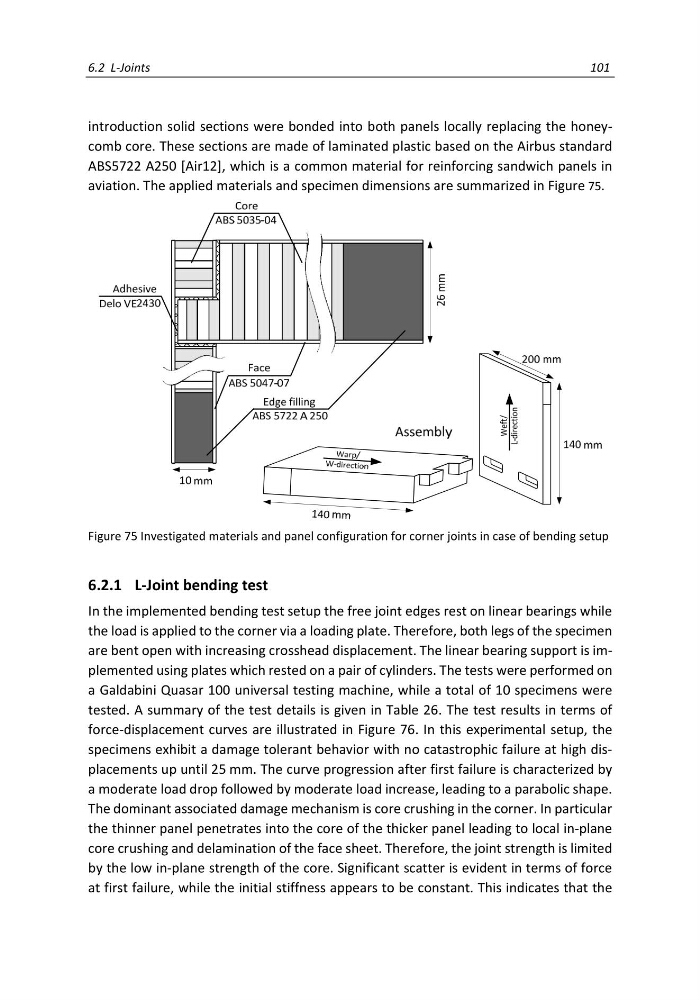
introduction solid sections were bonded into both panels locally replacing the honeycomb core. These sections are made of laminated plastic based on the Airbus standard
ABS5722 A250 [Air12], which is a common material for reinforcing sandwich panels in
aviation. The applied materials and specimen dimensions are summarized in Figure 75.
6.2.1 L-Joint bending test
In the implemented bending test setup the free joint edges rest on linear bearings while
the load is applied to the corner via a loading plate. Therefore, both legs of the specimen
are bent open with increasing crosshead displacement. The linear bearing support is implemented using plates which rested on a pair of cylinders. The tests were performed on
a Galdabini Quasar 100 universal testing machine, while a total of 10 specimens were
tested. A summary of the test details is given in Table 26. The test results in terms of
force-displacement curves are illustrated in Figure 76. In this experimental setup, the
specimens exhibit a damage tolerant behavior with no catastrophic failure at high displacements up until 25 mm. The curve progression after first failure is characterized by
a moderate load drop followed by moderate load increase, leading to a parabolic shape.
The dominant associated damage mechanism is core crushing in the corner. In particular
the thinner panel penetrates into the core of the thicker panel leading to local in-plane
core crushing and delamination of the face sheet. Therefore, the joint strength is limited
by the low in-plane strength of the core. Significant scatter is evident in terms of force
at first failure, while the initial stiffness appears to be constant. This indicates that the
Figure 75 Investigated materials and panel configuration for corner joints in case of bending setup
101
introduction solid sections were bonded into both panels locally replacing the honeycomb core. These sections are made of laminated plastic based on the Airbus standard
ABS5722 A250 [Air12], which is a common material for reinforcing sandwich panels in
aviation. The applied materials and specimen dimensions are summarized in Figure 75.
6.2.1 L-Joint bending test
In the implemented bending test setup the free joint edges rest on linear bearings while
the load is applied to the corner via a loading plate. Therefore, both legs of the specimen
are bent open with increasing crosshead displacement. The linear bearing support is implemented using plates which rested on a pair of cylinders. The tests were performed on
a Galdabini Quasar 100 universal testing machine, while a total of 10 specimens were
tested. A summary of the test details is given in Table 26. The test results in terms of
force-displacement curves are illustrated in Figure 76. In this experimental setup, the
specimens exhibit a damage tolerant behavior with no catastrophic failure at high displacements up until 25 mm. The curve progression after first failure is characterized by
a moderate load drop followed by moderate load increase, leading to a parabolic shape.
The dominant associated damage mechanism is core crushing in the corner. In particular
the thinner panel penetrates into the core of the thicker panel leading to local in-plane
core crushing and delamination of the face sheet. Therefore, the joint strength is limited
by the low in-plane strength of the core. Significant scatter is evident in terms of force
at first failure, while the initial stiffness appears to be constant. This indicates that the
Figure 75 Investigated materials and panel configuration for corner joints in case of bending setup