

6.1 Threaded inserts perpendicular to the face sheet
99
6.1.2 In-plane tension (shear)
The in-plane tension test is also referred to as shear or parallel tension test. Analogous
to the pull-out test there are no clearly defined test standards, however there are references in the literature. For instance, the IDH [ESA11] suggests two setups, both of which
are found in the reviewed technical literature. In the present work the shear test is
roughly based on the ASTM F606-95b [AST95]. This test requires rectangular specimens
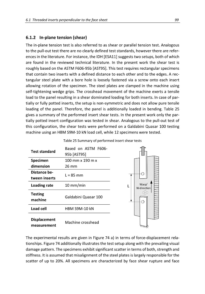
that contain two inserts with a defined distance to each other and to the edges. A rectangular steel plate with a bore hole is loosely fastened via a screw onto each insert
allowing rotation of the specimen. The steel plates are clamped in the machine using
self-tightening wedge grips. The crosshead movement of the machine exerts a tensile
load to the panel resulting in a shear dominated loading for both inserts. In case of partially or fully potted inserts, the setup is non-symmetric and does not allow pure tensile
loading of the panel. Therefore, the panel is additionally loaded in bending. Table 25
gives a summary of the performed insert shear tests. In the present work only the partially potted insert configuration was tested in shear. Analogous to the pull-out test of
this configuration, the shear tests were performed on a Galdabini Quasar 100 testing
machine using an HBM S9M-10 kN load cell, while 12 specimens were tested.
Table 25 Summary of performed insert shear tests
Test standard
Based on ASTM F60695b [AST95]
Specimen
dimension
100 mm x 190 m x
26 mm
Distance between inserts
L = 85 mm
Loading rate
10 mm/min
Testing
machine
Galdabini Quasar 100
Load cell
HBM S9M-10 kN
Displacement
measurement
Machine crosshead
The experimental results are given in Figure 74 a) in terms of force-displacement relationships. Figure 74 additionally illustrates the test setup along with the prevailing visual
damage pattern. The specimens exhibit significant scatter in terms of both, strength and
stiffness. It is assumed that misalignment of the steel plates is largely responsible for the
scatter of up to 20%. All specimens are characterized by face shear rupture and face
99
6.1.2 In-plane tension (shear)
The in-plane tension test is also referred to as shear or parallel tension test. Analogous
to the pull-out test there are no clearly defined test standards, however there are references in the literature. For instance, the IDH [ESA11] suggests two setups, both of which
are found in the reviewed technical literature. In the present work the shear test is
roughly based on the ASTM F606-95b [AST95]. This test requires rectangular specimens
that contain two inserts with a defined distance to each other and to the edges. A rectangular steel plate with a bore hole is loosely fastened via a screw onto each insert
allowing rotation of the specimen. The steel plates are clamped in the machine using
self-tightening wedge grips. The crosshead movement of the machine exerts a tensile
load to the panel resulting in a shear dominated loading for both inserts. In case of partially or fully potted inserts, the setup is non-symmetric and does not allow pure tensile
loading of the panel. Therefore, the panel is additionally loaded in bending. Table 25
gives a summary of the performed insert shear tests. In the present work only the partially potted insert configuration was tested in shear. Analogous to the pull-out test of
this configuration, the shear tests were performed on a Galdabini Quasar 100 testing
machine using an HBM S9M-10 kN load cell, while 12 specimens were tested.
Table 25 Summary of performed insert shear tests
Test standard
Based on ASTM F60695b [AST95]
Specimen
dimension
100 mm x 190 m x
26 mm
Distance between inserts
L = 85 mm
Loading rate
10 mm/min
Testing
machine
Galdabini Quasar 100
Load cell
HBM S9M-10 kN
Displacement
measurement
Machine crosshead
The experimental results are given in Figure 74 a) in terms of force-displacement relationships. Figure 74 additionally illustrates the test setup along with the prevailing visual
damage pattern. The specimens exhibit significant scatter in terms of both, strength and
stiffness. It is assumed that misalignment of the steel plates is largely responsible for the
scatter of up to 20%. All specimens are characterized by face shear rupture and face