

3.3 Analysis of Deformation
83
Strain Transformation and Principal Strains
The Lagrangian strain tensor defines the state of strain, i.e., local deformation, at
any point in a body independently of any coordinate system. As with any tensor, if
the coordinate system changes, the strain components change but the strain tensor
does not. In 3D, therefore, the deformation is completely defined by nine (six
independent) strain components computed with respect to any one of an infinite
number of possible coordinate systems. In other words, by changing coordinate
systems, we simply are observing the same deformation from another point of view.
This section considers the mechanics of transforming strain components between
different coordinate systems, as well as how they depend on direction.
Strain Transformation Relations Sometimes it is desirable to compute strains in
coordinates other than those used to solve a given problem. For example, most finiteelement codes are based on Cartesian coordinates and report Cartesian components
of strain by default, regardless of the specific problem geometry. Hence, if such
a program is used to study, for example, inflation of an artery modeled as a
straight tube, we may want to examine strain components computed relative to
cylindrical coordinates, which are more relevant physiologically. This would require
transforming the strain components from Cartesian to cylindrical coordinates.
In Chap. 2, we developed coordinate transformation equations for vector and
tensor components. Since E is a second-order tensor, Eq. (2.48) 2 can be used to
transform strain components between any two orthogonal coordinate systems. The
following example illustrates the procedure for a two-dimensional problem.
Example 3.14 Consider a body in a state of plane strain relative to the X 3 -axis
(E 13 = E 23 = E 33 = 0). The Cartesian components E ij of the Lagrangian strain
tensor are given (i, j = 1, 2). Determine the strain components ¯
E ij relative to the
coordinate system ¯
X i obtained by rotating X 1 and X 2 through the angle θ about the
X 3 -axis.
Solution
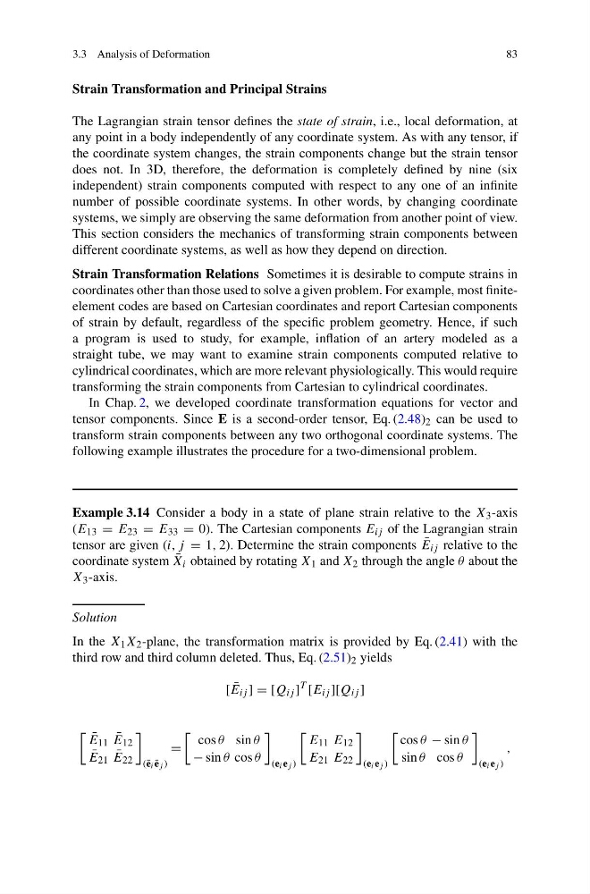
In the X 1 X 2 -plane, the transformation matrix is provided by Eq. (2.41) with the
third row and third column deleted. Thus, Eq. (2.51) 2 yields
[ ¯
E ij ] = [Q ij ]
T
[E ij ][Q ij ]
¯
E 11 ¯
E 12
¯
E 21 ¯
E 22
(¯ e i ¯
e j )
=
cos θ sin θ
− sin θ cos θ
(e i e j )
E 11 E 12
E 21 E 22
(e i e j )
cos θ − sin θ
sin θ cos θ
(e i e j )
,
83
Strain Transformation and Principal Strains
The Lagrangian strain tensor defines the state of strain, i.e., local deformation, at
any point in a body independently of any coordinate system. As with any tensor, if
the coordinate system changes, the strain components change but the strain tensor
does not. In 3D, therefore, the deformation is completely defined by nine (six
independent) strain components computed with respect to any one of an infinite
number of possible coordinate systems. In other words, by changing coordinate
systems, we simply are observing the same deformation from another point of view.
This section considers the mechanics of transforming strain components between
different coordinate systems, as well as how they depend on direction.
Strain Transformation Relations Sometimes it is desirable to compute strains in
coordinates other than those used to solve a given problem. For example, most finiteelement codes are based on Cartesian coordinates and report Cartesian components
of strain by default, regardless of the specific problem geometry. Hence, if such
a program is used to study, for example, inflation of an artery modeled as a
straight tube, we may want to examine strain components computed relative to
cylindrical coordinates, which are more relevant physiologically. This would require
transforming the strain components from Cartesian to cylindrical coordinates.
In Chap. 2, we developed coordinate transformation equations for vector and
tensor components. Since E is a second-order tensor, Eq. (2.48) 2 can be used to
transform strain components between any two orthogonal coordinate systems. The
following example illustrates the procedure for a two-dimensional problem.
Example 3.14 Consider a body in a state of plane strain relative to the X 3 -axis
(E 13 = E 23 = E 33 = 0). The Cartesian components E ij of the Lagrangian strain
tensor are given (i, j = 1, 2). Determine the strain components ¯
E ij relative to the
coordinate system ¯
X i obtained by rotating X 1 and X 2 through the angle θ about the
X 3 -axis.
Solution
In the X 1 X 2 -plane, the transformation matrix is provided by Eq. (2.41) with the
third row and third column deleted. Thus, Eq. (2.51) 2 yields
[ ¯
E ij ] = [Q ij ]
T
[E ij ][Q ij ]
¯
E 11 ¯
E 12
¯
E 21 ¯
E 22
(¯ e i ¯
e j )
=
cos θ sin θ
− sin θ cos θ
(e i e j )
E 11 E 12
E 21 E 22
(e i e j )
cos θ − sin θ
sin θ cos θ
(e i e j )
,