

472
8 Morphogenesis
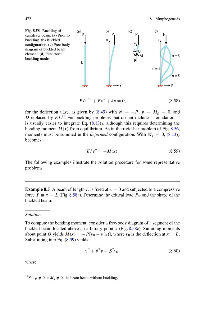
Fig. 8.58 Buckling of
cantilever beam. (a) Prior to
buckling. (b) Buckled
configuration. (c) Free-body
diagram of buckled beam
element. (d) First three
buckling modes
P
P
v 0
v
P
x
y
M
O
(a)
(b)
(c)
L
P
x
y
(d)
n = 5
n = 3
n = 1
P
EI v
+ P v
+ kv = 0,
(8.58)
for the deflection v(x), as given by (8.49) with N = −P , p = M g = 0, and
D replaced by EI . 15 For buckling problems that do not include a foundation, it
is usually easier to integrate Eq. (8.13) 3 , although this requires determining the
bending moment M(x) from equilibrium. As in the rigid-bar problem of Fig. 8.56,
moments must be summed in the deformed configuration. With M g = 0, (8.13) 3
becomes
EI v
= −M(x).
(8.59)
The following examples illustrate the solution procedure for some representative
problems.
Example 8.5 A beam of length L is fixed at x = 0 and subjected to a compressive
force P at x = L (Fig. 8.58a). Determine the critical load P cr and the shape of the
buckled beam.
Solution
To compute the bending moment, consider a free-body diagram of a segment of the
buckled beam located above an arbitrary point x (Fig. 8.58c). Summing moments
about point O yields M(x) = −P [v 0 − v(x)], where v 0 is the deflection at x = L.
Substituting into Eq. (8.59) yields
v
+ β
2 v = β
2 v 0 ,
(8.60)
where
15 For p = 0 or M g = 0, the beam bends without buckling.
8 Morphogenesis
Fig. 8.58 Buckling of
cantilever beam. (a) Prior to
buckling. (b) Buckled
configuration. (c) Free-body
diagram of buckled beam
element. (d) First three
buckling modes
P
P
v 0
v
P
x
y
M
O
(a)
(b)
(c)
L
P
x
y
(d)
n = 5
n = 3
n = 1
P
EI v
+ P v
+ kv = 0,
(8.58)
for the deflection v(x), as given by (8.49) with N = −P , p = M g = 0, and
D replaced by EI . 15 For buckling problems that do not include a foundation, it
is usually easier to integrate Eq. (8.13) 3 , although this requires determining the
bending moment M(x) from equilibrium. As in the rigid-bar problem of Fig. 8.56,
moments must be summed in the deformed configuration. With M g = 0, (8.13) 3
becomes
EI v
= −M(x).
(8.59)
The following examples illustrate the solution procedure for some representative
problems.
Example 8.5 A beam of length L is fixed at x = 0 and subjected to a compressive
force P at x = L (Fig. 8.58a). Determine the critical load P cr and the shape of the
buckled beam.
Solution
To compute the bending moment, consider a free-body diagram of a segment of the
buckled beam located above an arbitrary point x (Fig. 8.58c). Summing moments
about point O yields M(x) = −P [v 0 − v(x)], where v 0 is the deflection at x = L.
Substituting into Eq. (8.59) yields
v
+ β
2 v = β
2 v 0 ,
(8.60)
where
15 For p = 0 or M g = 0, the beam bends without buckling.