

424
8 Morphogenesis
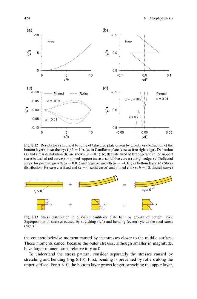
Fig. 8.12 Results for cylindrical bending of bilayered plate driven by growth or contraction of the
bottom layer (linear theory; L/ h = 10). (a, b) Cantilever plate (case a; free right edge). Deflection
(a) and stress distribution (b) are shown (a = 0.1). (c, d) Plate fixed at left edge and roller support
(case b; dashed red curves) or pinned support (case c; solid blue curves) at right edge. (c) Deflected
shape for positive growth (a = 0.01) and negative growth (a = −0.01) in bottom layer. (d) Stress
distributions for case c at fixed end (x = 0, solid curve) and pinned end (x/ h = 10, dashed curve)
g > 0
g > 0
Fig. 8.13 Stress distribution in bilayered cantilever plate bent by growth of bottom layer.
Superposition of stresses caused by stretching (left) and bending (center) yields the total stress
(right)
the counterclockwise moment caused by the stresses closer to the middle surface.
These moments cancel because the outer stresses, although smaller in magnitude,
have larger moment arms relative to y = 0.
To understand the stress pattern, consider separately the stresses caused by
stretching and bending (Fig. 8.13). First, bending is prevented by rollers along the
upper surface. For a > 0, the bottom layer grows longer, stretching the upper layer,
8 Morphogenesis
Fig. 8.12 Results for cylindrical bending of bilayered plate driven by growth or contraction of the
bottom layer (linear theory; L/ h = 10). (a, b) Cantilever plate (case a; free right edge). Deflection
(a) and stress distribution (b) are shown (a = 0.1). (c, d) Plate fixed at left edge and roller support
(case b; dashed red curves) or pinned support (case c; solid blue curves) at right edge. (c) Deflected
shape for positive growth (a = 0.01) and negative growth (a = −0.01) in bottom layer. (d) Stress
distributions for case c at fixed end (x = 0, solid curve) and pinned end (x/ h = 10, dashed curve)
g > 0
g > 0
Fig. 8.13 Stress distribution in bilayered cantilever plate bent by growth of bottom layer.
Superposition of stresses caused by stretching (left) and bending (center) yields the total stress
(right)
the counterclockwise moment caused by the stresses closer to the middle surface.
These moments cancel because the outer stresses, although smaller in magnitude,
have larger moment arms relative to y = 0.
To understand the stress pattern, consider separately the stresses caused by
stretching and bending (Fig. 8.13). First, bending is prevented by rollers along the
upper surface. For a > 0, the bottom layer grows longer, stretching the upper layer,