

420
8 Morphogenesis
the zero-stress configuration for each differential slice of the plate to become wedgeshaped. Since the pieces have planar faces, they fit together to create the bent
plate without requiring elastic deformation (Fig. 8.10d). In contrast, the nonlinear
(cubic) distribution causes the stress-free faces to become curved so they cannot
be reassembled without further deformation (note the end effects in Fig. 8.10d for
n = 3). Figure 8.10b shows the stress in the deformed plate for this case.
In both cases, the plate bends upward for a > 0 (Fig. 8.10c). This behavior is
consistent with the specified growth being positive in the lower half and negative in
the upper half of the plate (Fig. 8.10a). This pattern causes the bottom of the plate
to lengthen and the top to shorten, causing the plate to bend upward. Obviously, the
plate bends downward for a < 0.
A nonlinear finite-element model also yields σ = 0 for n = 1 and a stress
distribution for n = 3 that hardly can be distinguished from that given by
the linear theory (Fig. 8.10b). And, like the linear model, the nonlinear model
predicts a circular shape (Fig. 8.10c). Significant differences in deflection occur
toward the free edge of the plate, however, where large rotation causes the linear
approximation for curvature to become woefully inaccurate. The relatively accurate
stress distribution given by the linear model can be attributed to the fact that the peak
bending strain κh/2 in thin plates (small h) can remain small even when curvature
is large, e.g., consider bending of a piece of paper.
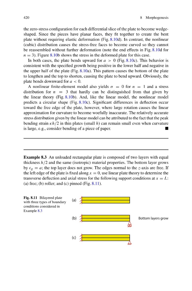
Example 8.3 An unloaded rectangular plate is composed of two layers with equal
thickness h/2 and the same (isotropic) material properties. The bottom layer grows
by g = a; the top layer does not grow. The edges normal to the z-axis are free. If
the left edge of the plate is fixed along x = 0, use linear plate theory to determine the
transverse deflection and axial stress for the following support conditions at x = L:
(a) free; (b) roller; and (c) pinned (Fig. 8.11).
Fig. 8.11 Bilayered plate
with three types of boundary
conditions considered in
Example 8.3
(a)
(c)
(b)
Bottom layers grow
8 Morphogenesis
the zero-stress configuration for each differential slice of the plate to become wedgeshaped. Since the pieces have planar faces, they fit together to create the bent
plate without requiring elastic deformation (Fig. 8.10d). In contrast, the nonlinear
(cubic) distribution causes the stress-free faces to become curved so they cannot
be reassembled without further deformation (note the end effects in Fig. 8.10d for
n = 3). Figure 8.10b shows the stress in the deformed plate for this case.
In both cases, the plate bends upward for a > 0 (Fig. 8.10c). This behavior is
consistent with the specified growth being positive in the lower half and negative in
the upper half of the plate (Fig. 8.10a). This pattern causes the bottom of the plate
to lengthen and the top to shorten, causing the plate to bend upward. Obviously, the
plate bends downward for a < 0.
A nonlinear finite-element model also yields σ = 0 for n = 1 and a stress
distribution for n = 3 that hardly can be distinguished from that given by
the linear theory (Fig. 8.10b). And, like the linear model, the nonlinear model
predicts a circular shape (Fig. 8.10c). Significant differences in deflection occur
toward the free edge of the plate, however, where large rotation causes the linear
approximation for curvature to become woefully inaccurate. The relatively accurate
stress distribution given by the linear model can be attributed to the fact that the peak
bending strain κh/2 in thin plates (small h) can remain small even when curvature
is large, e.g., consider bending of a piece of paper.
Example 8.3 An unloaded rectangular plate is composed of two layers with equal
thickness h/2 and the same (isotropic) material properties. The bottom layer grows
by g = a; the top layer does not grow. The edges normal to the z-axis are free. If
the left edge of the plate is fixed along x = 0, use linear plate theory to determine the
transverse deflection and axial stress for the following support conditions at x = L:
(a) free; (b) roller; and (c) pinned (Fig. 8.11).
Fig. 8.11 Bilayered plate
with three types of boundary
conditions considered in
Example 8.3
(a)
(c)
(b)
Bottom layers grow