

368
7 Remodeling
current configuration. For simplicity, the other configurations in Fig. 6.10 are not
shown.
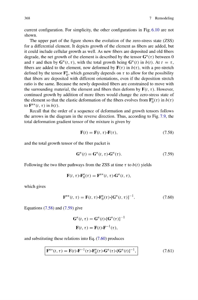
The upper part of the figure shows the evolution of the zero-stress state (ZSS)
for a differential element. It depicts growth of the element as fibers are added, but
it could include cellular growth as well. As new fibers are deposited and old fibers
degrade, the net growth of the element is described by the tensor G n (τ ) between 0
and τ and then by G n (t, τ ), with the total growth being G n (t) in b(t). At t = τ ,
fibers are added to the element, now deformed by F(τ ) in b(τ ), with a pre-stretch
defined by the tensor F n
0 , which generally depends on τ to allow for the possibility
that fibers are deposited with different orientations, even if the deposition stretch
ratio is the same. Because the newly deposited fibers are constrained to move with
the surrounding material, the element and fibers then deform by F(t, τ ). However,
continued growth by addition of more fibers would change the zero-stress state of
the element so that the elastic deformation of the fibers evolves from F n
0 (τ ) in b(τ )
to F n∗ (t, τ ) in b(t).
Recall that the order of a sequence of deformation and growth tensors follows
the arrows in the diagram in the reverse direction. Thus, according to Fig. 7.9, the
total deformation gradient tensor of the mixture is given by
F(t) = F(t, τ )·F(τ ),
(7.58)
and the total growth tensor of the fiber packet is
G
n (t) = G
n (t, τ )·G
n (τ ).
(7.59)
Following the two fiber pathways from the ZSS at time τ to b(t) yields
F(t, τ )·F
n
0 (τ ) = F
n∗ (t, τ )·G
n (t, τ ),
which gives
F
n∗ (t, τ ) = F(t, τ )·F
n
0 (τ )·[G
n (t, τ )]
−1 .
(7.60)
Equations (7.58) and (7.59) give
G
n (t, τ ) = G
n (t)·[G
n (τ )]
−1
F(t, τ ) = F(t)·F
−1 (τ ),
and substituting these relations into Eq. (7.60) produces
F n∗ (t, τ ) = F(t)·F −1 (τ )·F n
0 (τ )·G n (τ )·[G n (t)] −1 ,
(7.61)
7 Remodeling
current configuration. For simplicity, the other configurations in Fig. 6.10 are not
shown.
The upper part of the figure shows the evolution of the zero-stress state (ZSS)
for a differential element. It depicts growth of the element as fibers are added, but
it could include cellular growth as well. As new fibers are deposited and old fibers
degrade, the net growth of the element is described by the tensor G n (τ ) between 0
and τ and then by G n (t, τ ), with the total growth being G n (t) in b(t). At t = τ ,
fibers are added to the element, now deformed by F(τ ) in b(τ ), with a pre-stretch
defined by the tensor F n
0 , which generally depends on τ to allow for the possibility
that fibers are deposited with different orientations, even if the deposition stretch
ratio is the same. Because the newly deposited fibers are constrained to move with
the surrounding material, the element and fibers then deform by F(t, τ ). However,
continued growth by addition of more fibers would change the zero-stress state of
the element so that the elastic deformation of the fibers evolves from F n
0 (τ ) in b(τ )
to F n∗ (t, τ ) in b(t).
Recall that the order of a sequence of deformation and growth tensors follows
the arrows in the diagram in the reverse direction. Thus, according to Fig. 7.9, the
total deformation gradient tensor of the mixture is given by
F(t) = F(t, τ )·F(τ ),
(7.58)
and the total growth tensor of the fiber packet is
G
n (t) = G
n (t, τ )·G
n (τ ).
(7.59)
Following the two fiber pathways from the ZSS at time τ to b(t) yields
F(t, τ )·F
n
0 (τ ) = F
n∗ (t, τ )·G
n (t, τ ),
which gives
F
n∗ (t, τ ) = F(t, τ )·F
n
0 (τ )·[G
n (t, τ )]
−1 .
(7.60)
Equations (7.58) and (7.59) give
G
n (t, τ ) = G
n (t)·[G
n (τ )]
−1
F(t, τ ) = F(t)·F
−1 (τ ),
and substituting these relations into Eq. (7.60) produces
F n∗ (t, τ ) = F(t)·F −1 (τ )·F n
0 (τ )·G n (τ )·[G n (t)] −1 ,
(7.61)