

326
6 Growth
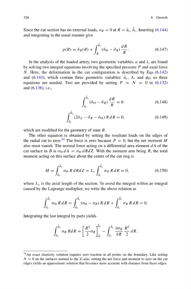
Since the cut section has no external loads, σ R = 0 at R = ˆ
a c , ˆ
b c . Inserting (6.144)
and integrating in the usual manner give
p(R) = ¯
σ R (R) +
ˆ
b c
R
( ¯
σ − ¯
σ R )
dR
R
.
(6.147)
In the analysis of the loaded artery, two geometric variables, a and λ, are found
by solving two integral equations involving the specified pressure P and axial force
N . Here, the deformation in the cut configuration is described by Eqs. (6.142)
and (6.143), which contain three geometric variables: ˆ
a c , , and φ 0 ; so three
equations are needed. Two are provided by setting P = N = 0 in (6.132)
and (6.138), i.e.,
ˆ
b c
ˆ
a c
( ¯
σ − ¯
σ R )
dR
R
= 0
(6.148)
ˆ
b c
ˆ
a c
(2 ¯
σ Z − ¯
σ R − ¯
σ ) R dR = 0,
(6.149)
which are modified for the geometry of state B.
The other equation is obtained by setting the resultant loads on the edges of
the radial cut to zero. 14 The force is zero because P = 0, but the net moment M
also must vanish. The normal force acting on a differential area element dA of the
cut surface in B is σ dA = σ dRdZ. With the moment arm being R, the total
moment acting on this surface about the center of the cut ring is
M =
ˆ
b c
ˆ
a c
σ R dRdZ = L c
ˆ
b c
ˆ
a c
σ R dR = 0,
(6.150)
where L c is the axial length of the section. To avoid the integral within an integral
caused by the Lagrange multiplier, we write the above relation as
ˆ
b c
ˆ
a c
σ R dR =
ˆ
b c
ˆ
a c
(σ − σ R ) R dR +
ˆ
b c
ˆ
a c
σ R R dR = 0.
Integrating the last integral by parts yields
ˆ
b c
ˆ
a c
σ R RdR =
R 2
2
σ R
ˆ
b c
ˆ
a c
−
ˆ
b c
ˆ
a c
∂σ R
∂R
R 2
2
dR.
14 An exact elasticity solution requires zero traction at all points on the boundary. Like setting
N = 0 on the surfaces normal to the Z-axis, setting the net force and moment to zero on the cut
edges yields an approximate solution that becomes more accurate with distance from these edges.
6 Growth
Since the cut section has no external loads, σ R = 0 at R = ˆ
a c , ˆ
b c . Inserting (6.144)
and integrating in the usual manner give
p(R) = ¯
σ R (R) +
ˆ
b c
R
( ¯
σ − ¯
σ R )
dR
R
.
(6.147)
In the analysis of the loaded artery, two geometric variables, a and λ, are found
by solving two integral equations involving the specified pressure P and axial force
N . Here, the deformation in the cut configuration is described by Eqs. (6.142)
and (6.143), which contain three geometric variables: ˆ
a c , , and φ 0 ; so three
equations are needed. Two are provided by setting P = N = 0 in (6.132)
and (6.138), i.e.,
ˆ
b c
ˆ
a c
( ¯
σ − ¯
σ R )
dR
R
= 0
(6.148)
ˆ
b c
ˆ
a c
(2 ¯
σ Z − ¯
σ R − ¯
σ ) R dR = 0,
(6.149)
which are modified for the geometry of state B.
The other equation is obtained by setting the resultant loads on the edges of
the radial cut to zero. 14 The force is zero because P = 0, but the net moment M
also must vanish. The normal force acting on a differential area element dA of the
cut surface in B is σ dA = σ dRdZ. With the moment arm being R, the total
moment acting on this surface about the center of the cut ring is
M =
ˆ
b c
ˆ
a c
σ R dRdZ = L c
ˆ
b c
ˆ
a c
σ R dR = 0,
(6.150)
where L c is the axial length of the section. To avoid the integral within an integral
caused by the Lagrange multiplier, we write the above relation as
ˆ
b c
ˆ
a c
σ R dR =
ˆ
b c
ˆ
a c
(σ − σ R ) R dR +
ˆ
b c
ˆ
a c
σ R R dR = 0.
Integrating the last integral by parts yields
ˆ
b c
ˆ
a c
σ R RdR =
R 2
2
σ R
ˆ
b c
ˆ
a c
−
ˆ
b c
ˆ
a c
∂σ R
∂R
R 2
2
dR.
14 An exact elasticity solution requires zero traction at all points on the boundary. Like setting
N = 0 on the surfaces normal to the Z-axis, setting the net force and moment to zero on the cut
edges yields an approximate solution that becomes more accurate with distance from these edges.