

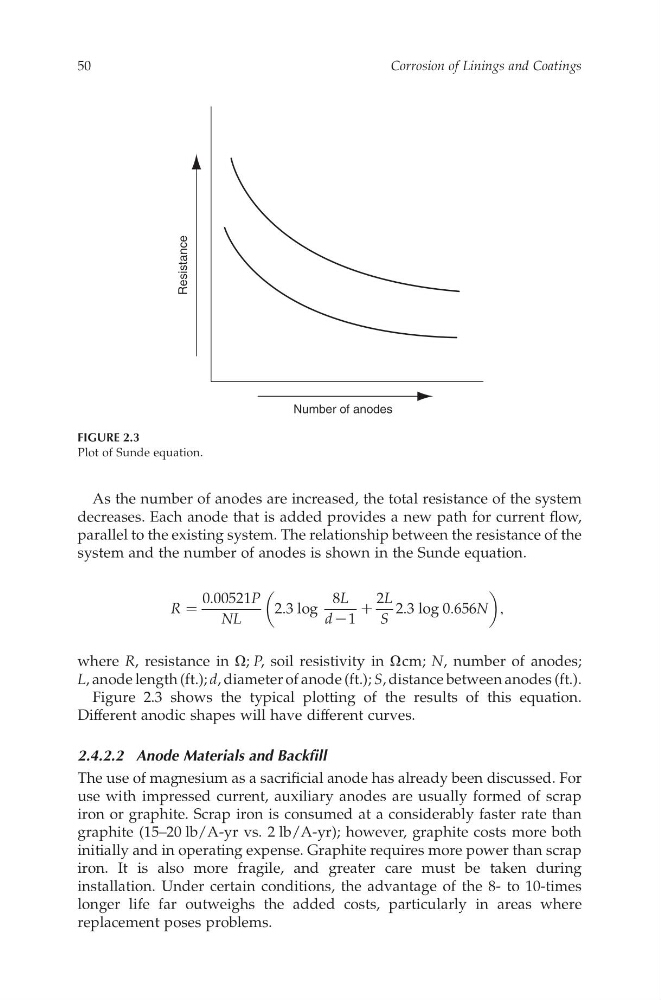
As the number of anodes are increased,the total resistance of the system
decreases. Each anode that is added provides an ew pathf or current flow,
parallel to the existing system. The relationship between the resistance of the
system and the numberofa nodesiss hown in the Sunde equation.
R Z
0 : 00521P
NL
2 : 3log
8 L
d K 1
C
2 L
S
2 : 3log 0 : 656N
;
where R ,r esistance in O ; P ,s oil resistivity in O cm; N ,n umber of anodes;
L ,anode length (ft.); d ,diameter of anode(ft.); S ,distance betweenanodes (ft.).
Figure 2.3 shows the typical plotting of the results of this equation.
Different anodic shapes willh ave different curves.
2.4.2.2 Anode Materials and Backfill
The use of magnesium as asacrificial anode has already been discussed.For
use with impressed current, auxiliary anodes are usuallyf ormed of scrap
iron or graphite. Scrap iron is consumed at ac onsiderablyf aster rate than
graphite (15–20 lb/A-yr vs. 2lb/A-yr); however, graphite costs more both
initially and in operating expense. Graphite requiresmore power than scrap
iron. It is also more fragile, andg reater care must be takend uring
installation. Under certain conditions, the advantageo ft he 8- to 10-times
longer life far outweighs the added costs, particularly in areas where
replacement poses problems.
Number of anodes
Resistance
FIGURE 2.3
Plot of Sunde equation.
Corrosion of Linings and Coatings
50
CAT8247—CHAPTER 2—6/10/2006—12:05—SRIDHAR—XML MODEL B–pp. 43–54
decreases. Each anode that is added provides an ew pathf or current flow,
parallel to the existing system. The relationship between the resistance of the
system and the numberofa nodesiss hown in the Sunde equation.
R Z
0 : 00521P
NL
2 : 3log
8 L
d K 1
C
2 L
S
2 : 3log 0 : 656N
;
where R ,r esistance in O ; P ,s oil resistivity in O cm; N ,n umber of anodes;
L ,anode length (ft.); d ,diameter of anode(ft.); S ,distance betweenanodes (ft.).
Figure 2.3 shows the typical plotting of the results of this equation.
Different anodic shapes willh ave different curves.
2.4.2.2 Anode Materials and Backfill
The use of magnesium as asacrificial anode has already been discussed.For
use with impressed current, auxiliary anodes are usuallyf ormed of scrap
iron or graphite. Scrap iron is consumed at ac onsiderablyf aster rate than
graphite (15–20 lb/A-yr vs. 2lb/A-yr); however, graphite costs more both
initially and in operating expense. Graphite requiresmore power than scrap
iron. It is also more fragile, andg reater care must be takend uring
installation. Under certain conditions, the advantageo ft he 8- to 10-times
longer life far outweighs the added costs, particularly in areas where
replacement poses problems.
Number of anodes
Resistance
FIGURE 2.3
Plot of Sunde equation.
Corrosion of Linings and Coatings
50
CAT8247—CHAPTER 2—6/10/2006—12:05—SRIDHAR—XML MODEL B–pp. 43–54