

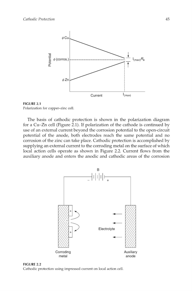
The basis of cathodic protection is shown in the polarization diagram
for aC u–Zn cell (Figure 2.1). If polarization of the cathode is continued by
use of an external current beyondthe corrosion potential to the open-circuit
potential of the anode, bothe lectrodes reach the same potential and no
corrosion of the zinc can take place. Cathodic protection is accomplished by
supplying an external current to the corroding metal on the surfaceofwhich
local action cells operate as shown in Figure 2.2.C urrent flowsf romt he
auxiliarya node and enters the anodica nd cathodic areas of the corrosion
I ( max) R e
I ( max)
Potential
Current
f Cu
f (corros.)
f Zn
FIGURE 2.1
Polarization for copper–zinc cell.
+
+
−
+
Corroding
metal
Auxiliary
anode
Electrolyte
B
−
FIGURE 2.2
Cathodic protection using impressed current on local action cell.
Cathodic Protection
45
CAT8247—CHAPTER 2—6/10/2006—12:05—SRIDHAR—XML MODEL B–pp. 43–54
for aC u–Zn cell (Figure 2.1). If polarization of the cathode is continued by
use of an external current beyondthe corrosion potential to the open-circuit
potential of the anode, bothe lectrodes reach the same potential and no
corrosion of the zinc can take place. Cathodic protection is accomplished by
supplying an external current to the corroding metal on the surfaceofwhich
local action cells operate as shown in Figure 2.2.C urrent flowsf romt he
auxiliarya node and enters the anodica nd cathodic areas of the corrosion
I ( max) R e
I ( max)
Potential
Current
f Cu
f (corros.)
f Zn
FIGURE 2.1
Polarization for copper–zinc cell.
+
+
−
+
Corroding
metal
Auxiliary
anode
Electrolyte
B
−
FIGURE 2.2
Cathodic protection using impressed current on local action cell.
Cathodic Protection
45
CAT8247—CHAPTER 2—6/10/2006—12:05—SRIDHAR—XML MODEL B–pp. 43–54