

Vectors 267
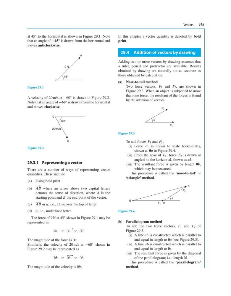
at 45
◦ to the horizontal is shown in Figure 29.1. Note
that an angle of +45 ◦ is drawn from the horizontal and
moves anticlockwise.
9 N
0
a
45Њ
Figure 29.1
A velocity of 20 m/s at −60 ◦ is shown in Figure 29.2.
Note that an angle of −60 ◦ is drawn from the horizontal
and moves clockwise.
60Њ
20 m/s
0
b
Figure 29.2
29.3.1 Representing a vector
There are a number of ways of representing vector
quantities. These include
(a) Using bold print.
(b)
− →
AB where an arrow above two capital letters
denotes the sense of direction, where A is the
starting point and B the end point of the vector.
(c) AB or a; i.e., a line over the top of letter.
(d) a; i.e., underlined letter.
The force of 9 N at 45 ◦ shown in Figure 29.1 may be
represented as
0a or
−→
0a or 0a
The magnitude of the force is 0a.
Similarly, the velocity of 20 m/s at −60 ◦ shown in
Figure 29.2 may be represented as
0b or
−→
0b or 0b
The magnitude of the velocity is 0b.
In this chapter a vector quantity is denoted by bold
print.
29.4 Addition of vectors by drawing
Adding two or more vectors by drawing assumes that
a ruler, pencil and protractor are available. Results
obtained by drawing are naturally not as accurate as
those obtained by calculation.
(a) Nose-to-tail method
Two force vectors, F 1 and F 2 , are shown in
Figure 29.3. When an object is subjected to more
than one force, the resultant of the forces is found
by the addition of vectors.
F 2
F 1
Figure 29.3
To add forces F 1 and F 2 ,
(i) Force F 1 is drawn to scale horizontally,
shown as 0a in Figure 29.4.
(ii) From the nose of F 1 , force F 2 is drawn at
angle θ to the horizontal, shown as ab.
(iii) The resultant force is given by length 0b,
which may be measured.
This procedure is called the ‘nose-to-tail’ or
‘triangle’ method.
F 2
F 1 a
b
0
Figure 29.4
(b) Parallelogram method
To add the two force vectors, F 1 and F 2 of
Figure 29.3,
(i) A line cb is constructed which is parallel to
and equal in length to 0a (see Figure 29.5).
(ii) A line ab is constructed which is parallel to
and equal in length to 0c.
(iii) The resultant force is given by the diagonal
of the parallelogram; i.e., length 0b.
This procedure is called the ‘parallelogram’
method.
at 45
◦ to the horizontal is shown in Figure 29.1. Note
that an angle of +45 ◦ is drawn from the horizontal and
moves anticlockwise.
9 N
0
a
45Њ
Figure 29.1
A velocity of 20 m/s at −60 ◦ is shown in Figure 29.2.
Note that an angle of −60 ◦ is drawn from the horizontal
and moves clockwise.
60Њ
20 m/s
0
b
Figure 29.2
29.3.1 Representing a vector
There are a number of ways of representing vector
quantities. These include
(a) Using bold print.
(b)
− →
AB where an arrow above two capital letters
denotes the sense of direction, where A is the
starting point and B the end point of the vector.
(c) AB or a; i.e., a line over the top of letter.
(d) a; i.e., underlined letter.
The force of 9 N at 45 ◦ shown in Figure 29.1 may be
represented as
0a or
−→
0a or 0a
The magnitude of the force is 0a.
Similarly, the velocity of 20 m/s at −60 ◦ shown in
Figure 29.2 may be represented as
0b or
−→
0b or 0b
The magnitude of the velocity is 0b.
In this chapter a vector quantity is denoted by bold
print.
29.4 Addition of vectors by drawing
Adding two or more vectors by drawing assumes that
a ruler, pencil and protractor are available. Results
obtained by drawing are naturally not as accurate as
those obtained by calculation.
(a) Nose-to-tail method
Two force vectors, F 1 and F 2 , are shown in
Figure 29.3. When an object is subjected to more
than one force, the resultant of the forces is found
by the addition of vectors.
F 2
F 1
Figure 29.3
To add forces F 1 and F 2 ,
(i) Force F 1 is drawn to scale horizontally,
shown as 0a in Figure 29.4.
(ii) From the nose of F 1 , force F 2 is drawn at
angle θ to the horizontal, shown as ab.
(iii) The resultant force is given by length 0b,
which may be measured.
This procedure is called the ‘nose-to-tail’ or
‘triangle’ method.
F 2
F 1 a
b
0
Figure 29.4
(b) Parallelogram method
To add the two force vectors, F 1 and F 2 of
Figure 29.3,
(i) A line cb is constructed which is parallel to
and equal in length to 0a (see Figure 29.5).
(ii) A line ab is constructed which is parallel to
and equal in length to 0c.
(iii) The resultant force is given by the diagonal
of the parallelogram; i.e., length 0b.
This procedure is called the ‘parallelogram’
method.