

744
Modeling Arithmetic, Computation, and Languages
table 9.10
present state
next state
output
present input
0
1
0
1
3
1
1
2
0
0
2
1
3
0
3
2
1
0
sequential networks and finite-state Machines
The output of a finite-state machine is a function of its present state, and the present state of the machine is a function of past inputs. Thus, the states of a machine
have certain memory capabilities. In the combinational networks of Chapter 8,
which use AND gates, OR gates, and inverters, the output is virtually instantaneous and a function only of the present input. To build a finite-state machine we
need one additional element that provides the memory missing from our previous
logic networks.
A delay element is the simplest of a class of elements known as flip-flops. It
is regulated by a clock, has a single binary input, and its output at time t + 1 is
the input signal it received at time t. The delay element is therefore a “memory
device” that captures input for the duration of one clock pulse. Figure 9.11 represents the delay element at time t + 1, with the signal propagating from right to
left. When the delay element is receiving an input of d(t + 1), the output is the
previous input d(t).
d(t)
d(tϩ1)
figure 9.11
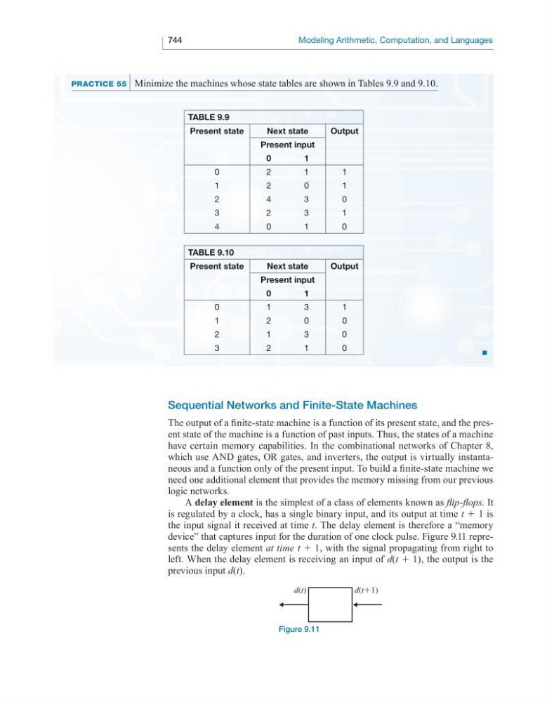
PrACtiCe 55 Minimize the machines whose state tables are shown in Tables 9.9 and 9.10.
■
table 9.9
present state
next state
output
present input
0
1
0
2
1
1
1
2
0
1
2
4
3
0
3
2
3
1
4
0
1
0