

Section 9.3 Finite-State Machines
733
The output (written right to left) is 1000 when we ignore the initial 0, which does
not reflect the action of any input. Converting this arithmetic to decimal form, we
have computed 3 + 5 = 8. Note the symmetry of this machine with respect to the
inputs of 10 and 01, reflecting that binary addition is commutative.
PrACtiCe 47 Compute the sum of 01110110 and 01010101 by using the binary adder machine of
Figure 9.5.
■
recognition
We have already noted that a given input signal may affect the behavior of a
finite-state machine for longer than just one clock pulse. Because of the (limited)
memory of past inputs represented by the states of a machine, we can use these
machines as recognizers. A machine can be built to recognize, say by producing
an output of 1, when the input it has received matches a certain description. We
will soon discuss more fully the capabilities of finite-state machines as recognizers.
Here we will simply construct some examples.
example 30
When binary data are transmitted (or stored) as strings of bits, an extra bit is often
tacked onto the end of each string as a parity bit. Under an even parity scheme, the
parity bit (a 0 or a 1) is chosen so that the total number of 1s in the string, including
the parity bit, is an even number. Under an odd parity scheme, the parity bit is chosen so that the total number of 1s in the string is odd. When the string is received,
its parity is checked. Assuming an even parity scheme, if the parity of the received
string is not even, then an error has occurred in transmitting the string, and a request for retransmission can be made. A parity bit therefore serves as a simple
single-error-detection mechanism. (Note that a parity bit does not detect errors in 2
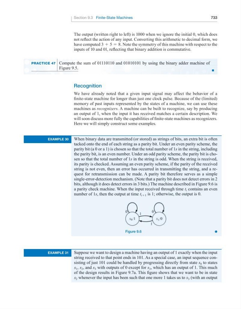
bits, although it does detect errors in 3 bits.) The machine described in Figure 9.6 is
a parity check machine. When the input received through time t i contains an even
number of 1s, then the output at time t i+1 is 1; otherwise, the output is 0.
figure 9.6
example 31
Suppose we want to design a machine having an output of 1 exactly when the input
string received to that point ends in 101. As a special case, an input sequence consisting of just 101 could be handled by progressing directly from state s 0 to states
s 1 , s 2 , and s 3 with outputs of 0 except for s 3 , which has an output of 1. This much
of the design results in Figure 9.7a. This figure shows that we want to be in state
s 2 whenever the input has been such that one more 1 takes us to s 3 (with an output