

730
Modeling Arithmetic, Computation, and Languages
example 29
A finite-state machine M is described as follows: S = 5s 0 , s 1 , s 2 6, I = 50, 16,
O = 50, 16. Because the two functions f S and f O act on finite domains, they can be
defined by a state table, as in Table 9.1. The machine M begins in state s 0 , which
has an output of 0. If the first input symbol is a 0, the next state of the machine is
then s 1 , which has an output of 1.
table 9.1
present state
next state
output
present input
0
1
s 0
s 1
s 0
0
s 1
s 2
s 1
1
s 2
s 2
s 0
1
If the next input symbol is a 1, the machine stays in state s 1 with an output of 1. By
continuing this analysis, we see that an input sequence consisting of the characters
01101 (read left to right) would produce the following effect:
time
t 0 t 1 t 2 t 3 t 4 t 5
Input
0 1 1 0 1 –
State
s 0 s 1 s 1 s 1 s 2 s 0
Output
0 1 1 1 1 0
The initial 0 of the output string is spurious—it merely reflects the starting state,
not the result of any input. In a similar way, the input sequence 1010 produces an
output of 00111.
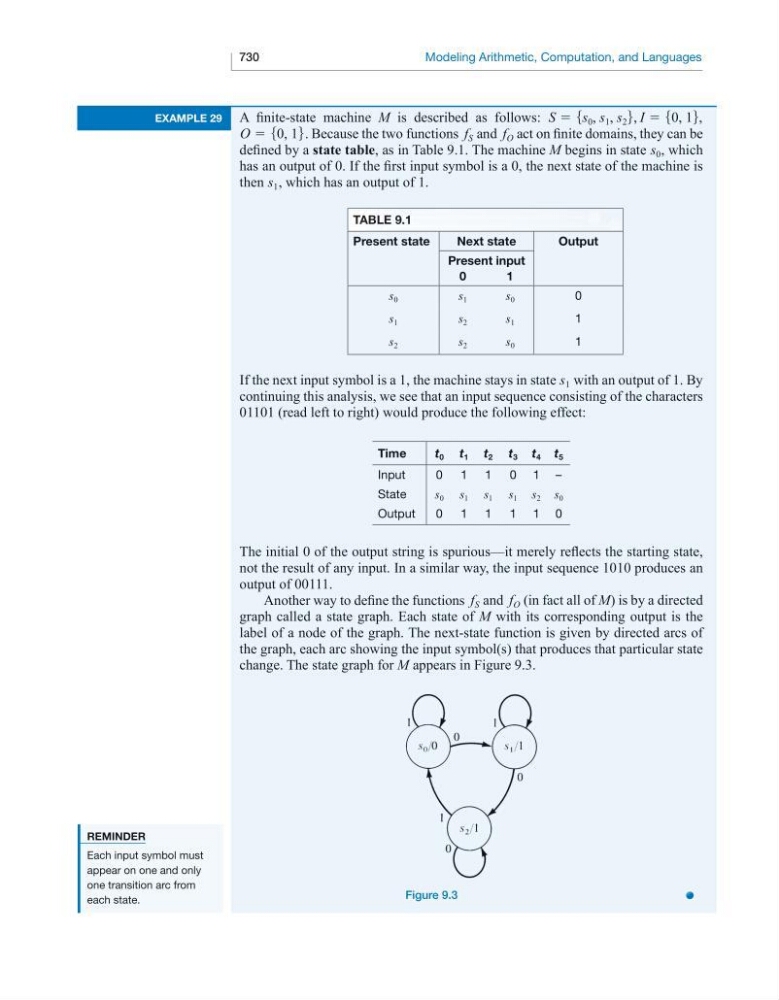
Another way to define the functions f S and f O (in fact all of M) is by a directed
graph called a state graph. Each state of M with its corresponding output is the
label of a node of the graph. The next-state function is given by directed arcs of
the graph, each arc showing the input symbol(s) that produces that particular state
change. The state graph for M appears in Figure 9.3.
figure 9.3
ReminDeR
Each input symbol must
appear on one and only
one transition arc from
each state.