

650
Boolean Algebra and Computer Logic
To add two n-bit binary numbers, we add column by column from the loworder to the high-order bits. The ith column (except for the very first column) has
as input its two bits x 1 and x 2 plus the carry bit from the addition of column i − 1
to its right. Thus we need a device incorporating the previous carry bit as input.
Such a device can be accomplished by adding x 1 and x 2 with a half-adder and then
adding the previous carry bit c i−1 (using another half-adder) to the result. Again, a
sum bit s and final carry bit c i are output, where c i is 1 if either half-adder produces
a 1 as its carry bit. The full-adder is shown in Figure 8.14b. The full-adder is thus
composed of two half-adders and an additional OR gate.
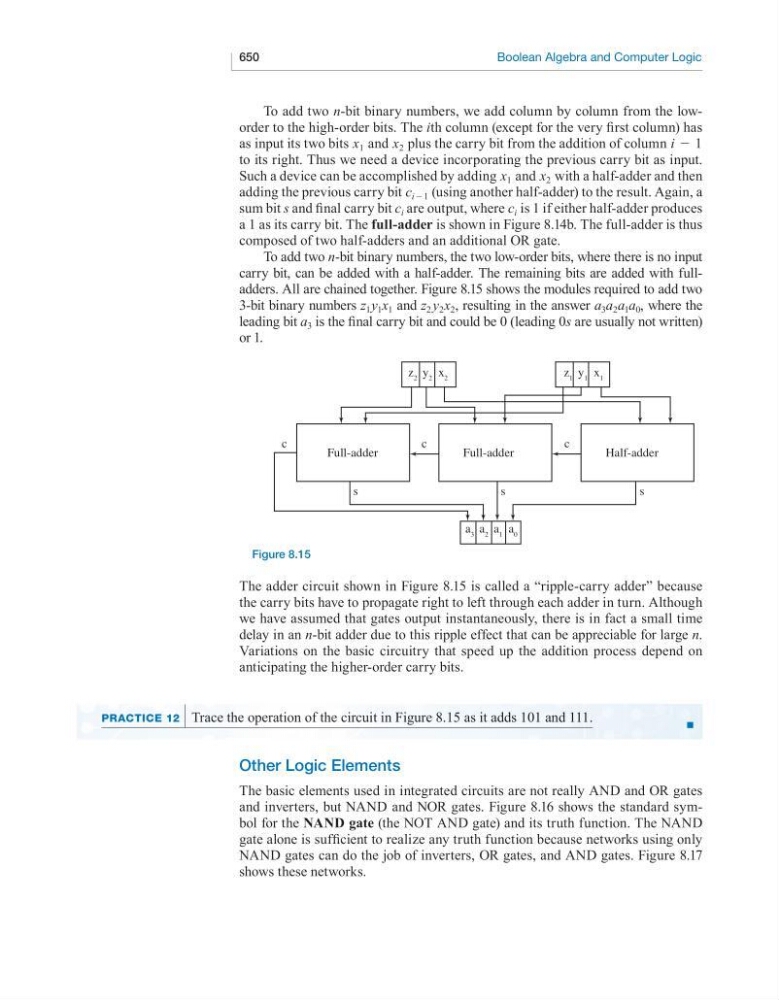
To add two n-bit binary numbers, the two low-order bits, where there is no input
carry bit, can be added with a half-adder. The remaining bits are added with fulladders. All are chained together. Figure 8.15 shows the modules required to add two
3-bit binary numbers z 1 y 1 x 1 and z 2 y 2 x 2 , resulting in the answer a 3 a 2 a 1 a 0 , where the
leading bit a 3 is the final carry bit and could be 0 (leading 0s are usually not written)
or 1.
Full-adder
s
z 2
a 3 a 2 a 1 a 0
y 2 x 2
z 1 y 1 x 1
c
c
c
s
s
Full-adder
Half-adder
Figure 8.15
The adder circuit shown in Figure 8.15 is called a “ripple-carry adder” because
the carry bits have to propagate right to left through each adder in turn. Although
we have assumed that gates output instantaneously, there is in fact a small time
delay in an n-bit adder due to this ripple effect that can be appreciable for large n.
Variations on the basic circuitry that speed up the addition process depend on
anticipating the higher-order carry bits.
■
Practice 12 Trace the operation of the circuit in Figure 8.15 as it adds 101 and 111.
Other Logic Elements
The basic elements used in integrated circuits are not really AND and OR gates
and inverters, but NAND and NOR gates. Figure 8.16 shows the standard symbol for the NAND gate (the NOT AND gate) and its truth function. The NAND
gate alone is sufficient to realize any truth function because networks using only
NAND gates can do the job of inverters, OR gates, and AND gates. Figure 8.17
shows these networks.