

Innovative Bridge Concept
5
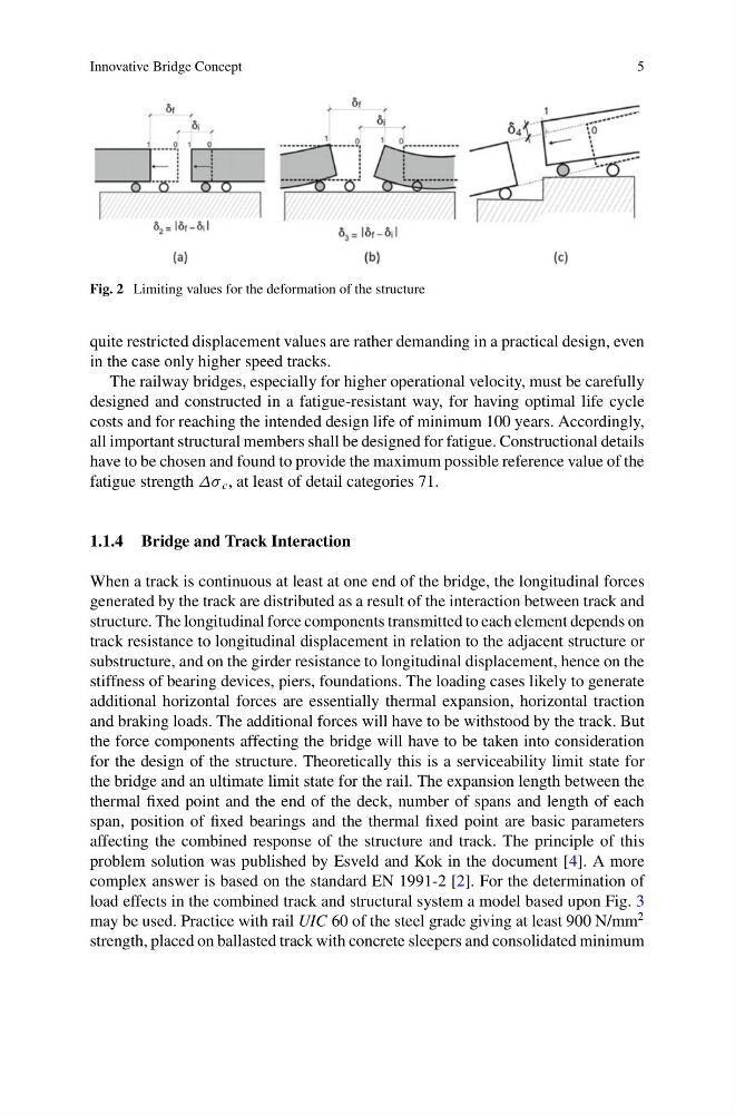
Fig. 2 Limiting values for the deformation of the structure
quite restricted displacement values are rather demanding in a practical design, even
in the case only higher speed tracks.
The railway bridges, especially for higher operational velocity, must be carefully
designed and constructed in a fatigue-resistant way, for having optimal life cycle
costs and for reaching the intended design life of minimum 100 years. Accordingly,
all important structural members shall be designed for fatigue. Constructional details
have to be chosen and found to provide the maximum possible reference value of the
fatigue strength Δσ c , at least of detail categories 71.
1.1.4 Bridge and Track Interaction
When a track is continuous at least at one end of the bridge, the longitudinal forces
generated by the track are distributed as a result of the interaction between track and
structure. The longitudinal force components transmitted to each element depends on
track resistance to longitudinal displacement in relation to the adjacent structure or
substructure, and on the girder resistance to longitudinal displacement, hence on the
stiffness of bearing devices, piers, foundations. The loading cases likely to generate
additional horizontal forces are essentially thermal expansion, horizontal traction
and braking loads. The additional forces will have to be withstood by the track. But
the force components affecting the bridge will have to be taken into consideration
for the design of the structure. Theoretically this is a serviceability limit state for
the bridge and an ultimate limit state for the rail. The expansion length between the
thermal fixed point and the end of the deck, number of spans and length of each
span, position of fixed bearings and the thermal fixed point are basic parameters
affecting the combined response of the structure and track. The principle of this
problem solution was published by Esveld and Kok in the document [4]. A more
complex answer is based on the standard EN 1991-2 [2]. For the determination of
load effects in the combined track and structural system a model based upon Fig. 3
may be used. Practice with rail UIC 60 of the steel grade giving at least 900 N/mm
2
strength, placed on ballasted track with concrete sleepers and consolidated minimum
5
Fig. 2 Limiting values for the deformation of the structure
quite restricted displacement values are rather demanding in a practical design, even
in the case only higher speed tracks.
The railway bridges, especially for higher operational velocity, must be carefully
designed and constructed in a fatigue-resistant way, for having optimal life cycle
costs and for reaching the intended design life of minimum 100 years. Accordingly,
all important structural members shall be designed for fatigue. Constructional details
have to be chosen and found to provide the maximum possible reference value of the
fatigue strength Δσ c , at least of detail categories 71.
1.1.4 Bridge and Track Interaction
When a track is continuous at least at one end of the bridge, the longitudinal forces
generated by the track are distributed as a result of the interaction between track and
structure. The longitudinal force components transmitted to each element depends on
track resistance to longitudinal displacement in relation to the adjacent structure or
substructure, and on the girder resistance to longitudinal displacement, hence on the
stiffness of bearing devices, piers, foundations. The loading cases likely to generate
additional horizontal forces are essentially thermal expansion, horizontal traction
and braking loads. The additional forces will have to be withstood by the track. But
the force components affecting the bridge will have to be taken into consideration
for the design of the structure. Theoretically this is a serviceability limit state for
the bridge and an ultimate limit state for the rail. The expansion length between the
thermal fixed point and the end of the deck, number of spans and length of each
span, position of fixed bearings and the thermal fixed point are basic parameters
affecting the combined response of the structure and track. The principle of this
problem solution was published by Esveld and Kok in the document [4]. A more
complex answer is based on the standard EN 1991-2 [2]. For the determination of
load effects in the combined track and structural system a model based upon Fig. 3
may be used. Practice with rail UIC 60 of the steel grade giving at least 900 N/mm
2
strength, placed on ballasted track with concrete sleepers and consolidated minimum