

Analog and Digital Filters
597
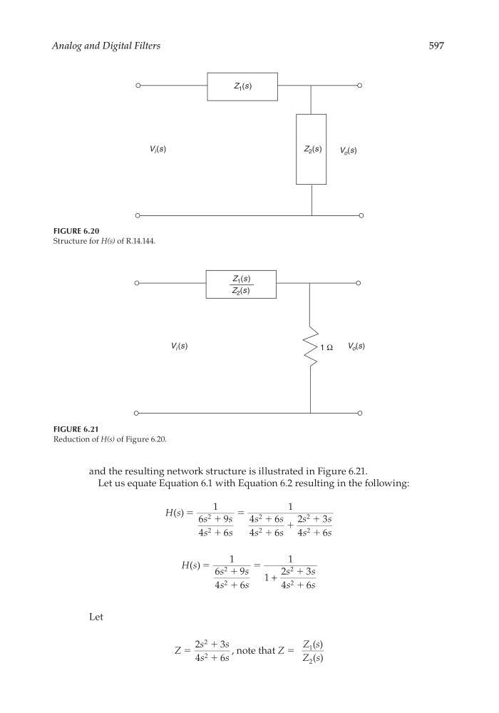
and the resulting network structure is illustrated in Figure 6.21.
Let us equate Equation 6.1 with Equation 6.2 resulting in the following:
H s
s
s
s
s
s
s
s
s
s
s
s
s
( ) ϭ
ϩ
ϩ
ϭ
ϩ
ϩ
ϩ
ϩ
ϩ
1
6
9
4
6
1
4
6
4
6
2
3
4
6
2
2
2
2
2
2
H s
s
s
s
s
s
s
s
s
( ) ϭ
ϩ
ϩ
ϭ
ϩ
ϩ
1
6
9
4
6
1
1
2
3
4
6
2
2
2
2
+
Let
Z
s
s
s
s
ϭ
ϩ
ϩ
2
3
4
6
2
2
, note that
( )
( )
1
2
Z
Z s
Z s
ϭ
FIGURE 6.20
Structure for H(s) of R.14.144.
Z 1 (s)
Z 2 (s)
V o (s)
V i (s)
FIGURE 6.21
Reduction of H(s) of Figure 6.20.
Z 1 (s)
Z 2 (s)
V i (s)
V o (s)
1 Ω
CRC_47760_CH006.indd 597
CRC_47760_CH006.indd 597
7/23/2008 2:26:41 PM
7/23/2008 2:26:41 PM